| File/s needed: |
| Click to download the Introductory [US units] tutorial model files. |
Add Arch Chamber
Since CAD does not represent Stormwater Controls (i.e. Ponds, Swales, Raingardens) as richly in Plan as InfoDrainage does, the Pipe Network that was imported is overly simplified and uses ‘dummy’ objects as placeholders for designers who are forced to split their work between several tools. To achieve proper Runoff Mitigation an Underground Detention Arch Chamber needs to be added, which can be easily done by converting the ‘dummy’ junction into a full Stormwater Control (SWC).
- Continue working on your model or open ID_US_Introduction_Project_Ch2.iddx.
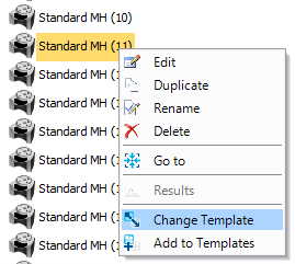
- Right-click Standard MH (11), on the Plan or under Junctions on Tree view, and select Change Template. We could change more than one object at once but on this occasion, we are only changing one manhole.
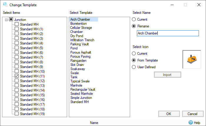
- Select Arch Chamber from the
Select Template list. Under
Select Name, select
Rename
and enter to Arch Chamber. Select OK to close the dialog.
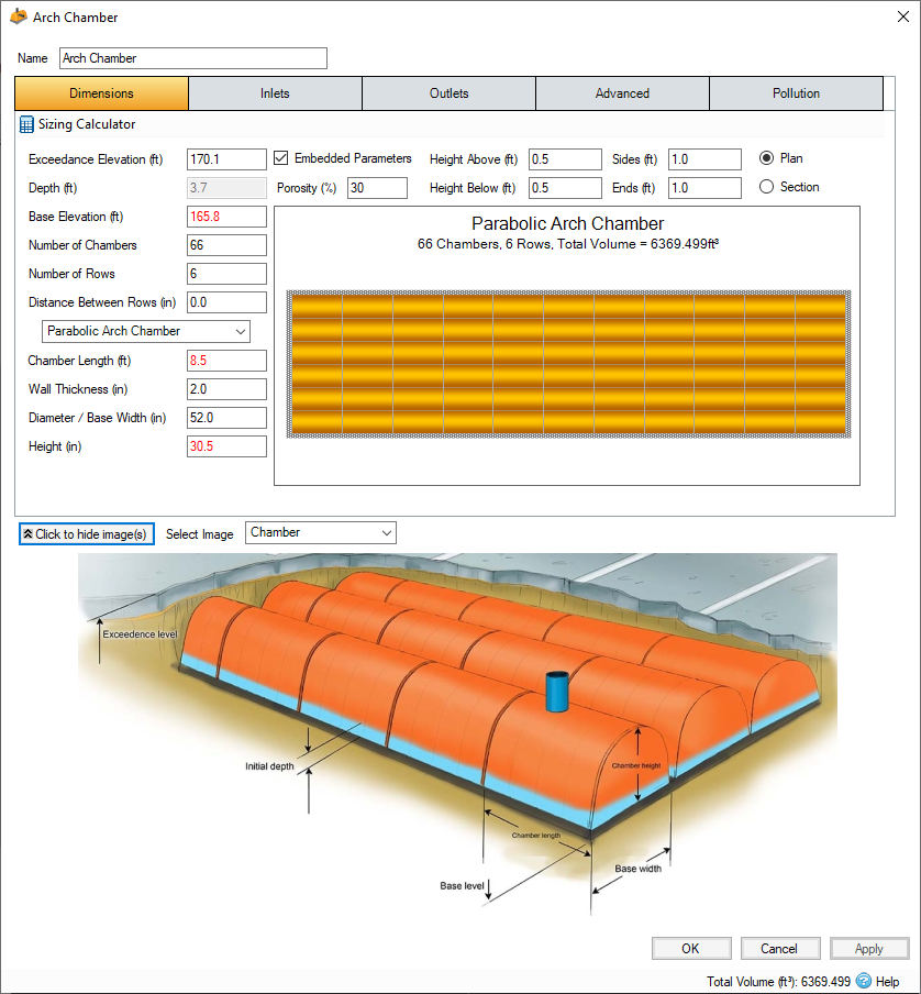
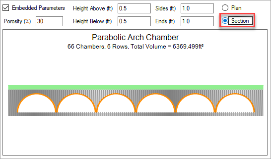
- Double-click or right-click and select Edit to review the Arch Chamber Stormwater Control (SWC) properties. This facility uses the Parabolic Arch Chamber configuration type and the individual chamber section lengths, wall thickness, diameter and height are all as noted in manufacturer specifications. Any change to input that would affect the facility extents will be represented in Plan, just like any changes to the Plan layout will update dimension details within the SWC properties. Use the Click to Show Images button in the lower left of the dialog to view a schematic of what the underground detention chambers looks like.
- The embedded parameters allow for the fill material above and around the chambers to be applied toward facility storage. Notice that the schematic view of the detention facility can be switched from Plan (top down) view to a Section (or an on-end profile) view.
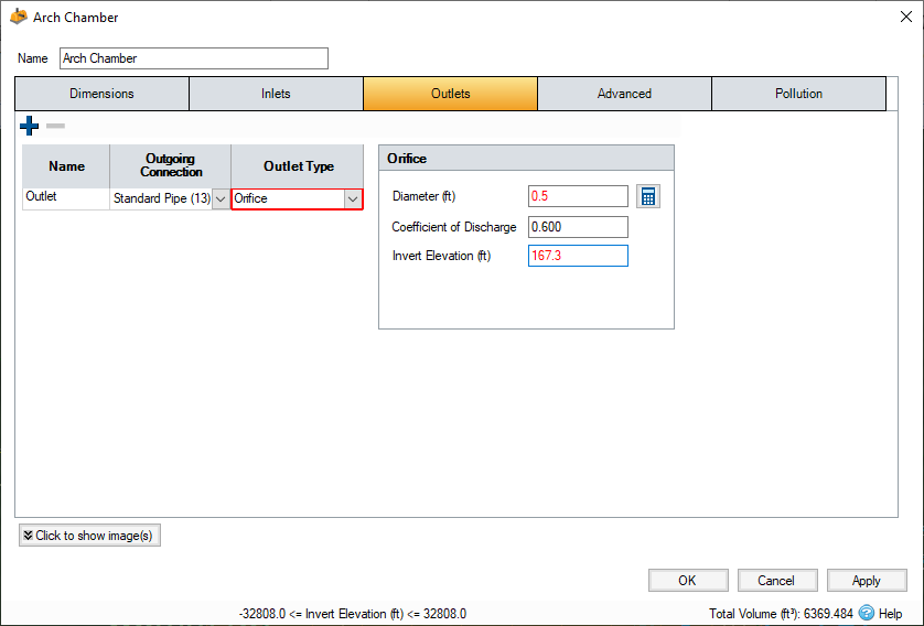
- Under the Outlets tab, from the Outlet Type drop down list, select Orifice and enter a Diameter
of 0.5 ft and set the Invert Elevation
to 167.3 ft. This will set an orifice 1.5 ft above the base of the Chambers. Select OK to close the SWC dialog.
Reconnect System
Since InfoDrainage allows for ‘AS-BUILD’ layout and details of stormwater systems, it is valuable to place the Inlets and Outlet of this facility at the real world proposed locations to ensure connection inverts, lengths, and slopes are accurate.
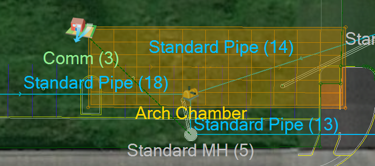
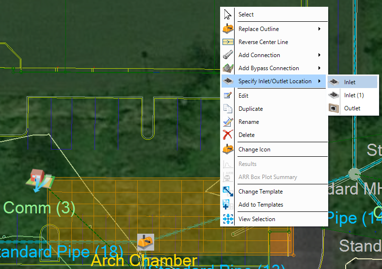
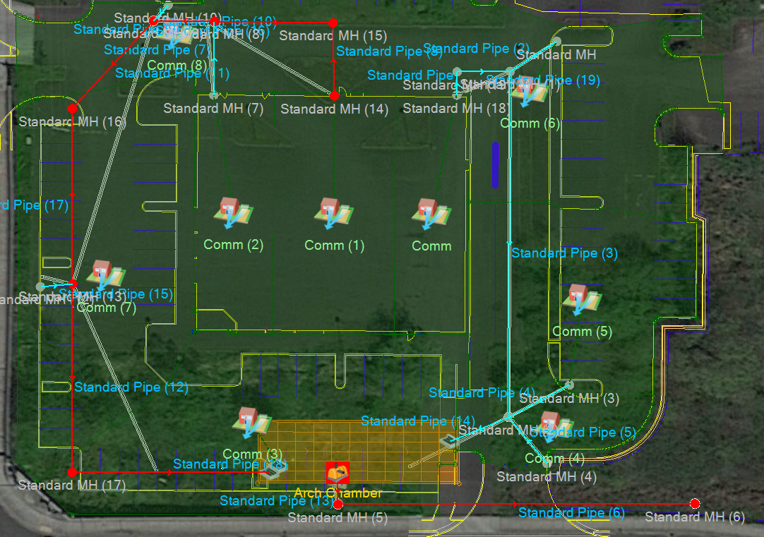
- Right-click the Arch Chamber SWC and select Specify Inlet/Outlet Location, select one of the Inlets/outlet. You can then drag and drop the Inlet/Outlet to the appropriate location. Repeat process for all objects until they are located as shown.

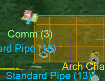
- When the Pipe Network was imported, any Junctions that fall on unconnected Inflow Areas are automatically connected to the adjacent Junction. If there are multiple Junctions imported on top of the same Inflow Area, only one will be connected, so it is important to review if all of the automatic connecting occurred as expected. In the case of Comm (3) and the Arch Chamber SWC, it appears that the Inflow Area connected automatically to the structure downstream of the Arch Chamber SWC. This can be easily updated by right-click on Comm (3) and select Reconnect Inflow. Then place the inlet next to the parking island as shown.

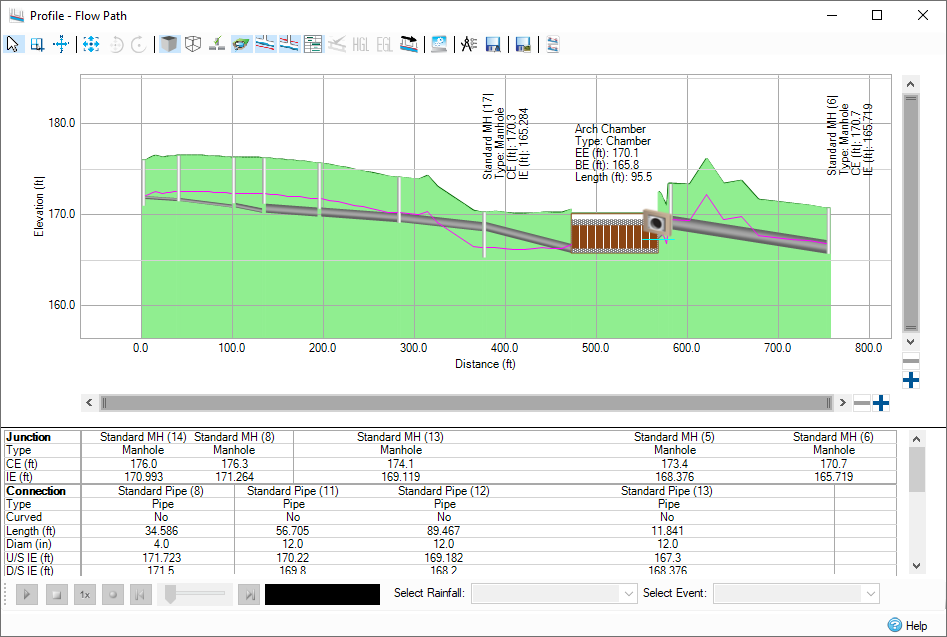
- Now that the Arch Chamber SWC has been configured, add a flow path as shown in order to view a Profile of the drainage system. Right-click
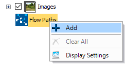
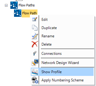
Flow Paths from the Tree View, select Add and click once on the Junction at the top-middle of the site then once at the downstream most Junction at the lower right corner of the site. Hit the Esc key to end the action, then right-click Flow Paths and select Show Profile.
Size Pipe Network
Now that the Arch Chamber SWC has been added and configured, Automatically Size the Pipe Network within the Connections.
- Double-click Connections
on the Tree View, or by selecting Connections on the Preliminary Sizing ribbon.


- Pipe Networks can be sized based on Flow Paths - select a Flow Path from the drop down list and notice that the Connections list is sorted with Connections and Branch Lines based on the Flow Path selection. Sizing will occur for all Connections contained in the Flow Path and all Branch Lines. Select Network Design Wizard to perform preliminary sizing of the Pipe Network.
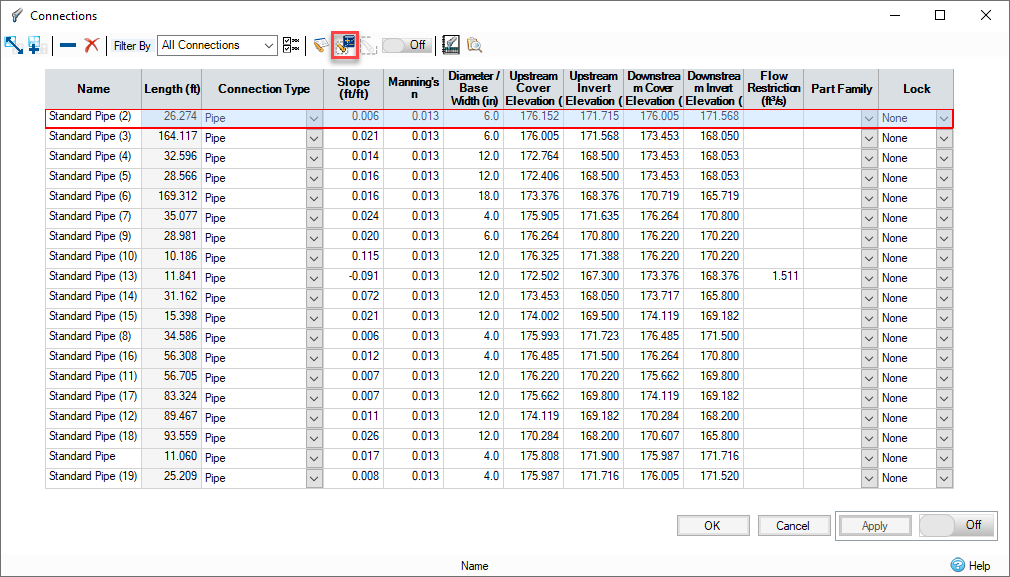
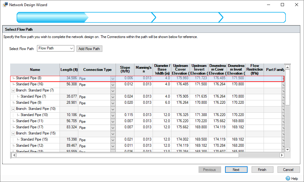
- Once the Network Design Wizard is opened, a new or existing Flow Path can be selected for sizing, including the entire Flow Path and all of its tributary branches. Since only one Flow Path has been created, simply select
Next to proceed to Flow Criteria.
- As the
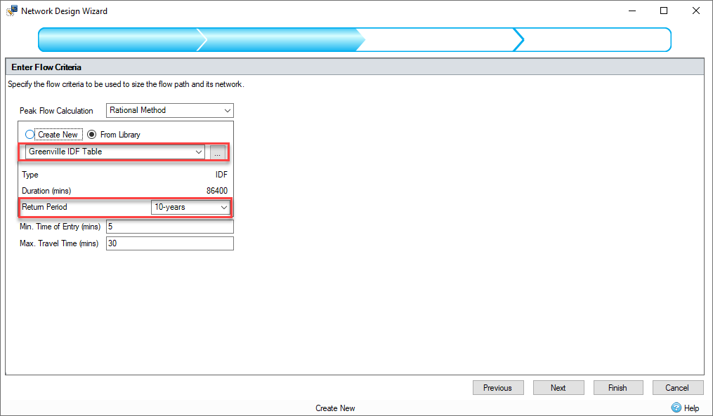
Network Design Wizard uses the Rational method for peak runoff flows based on the Preliminary Sizing input within the attached Inflow Areas, select the Greenville IDF Table as the Rainfall Source and select the 10 year return period as the event sizing for the pipe network. These Rainfall Sources can be reviewed under the Rainfall ribbon if desired. Click Next.
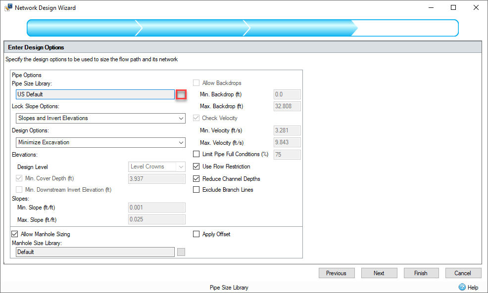
- The Design Options can be reviewed in the next step of the wizard. First click the square button next to
Pipe Size Library. A default Pipe Sizing Library has already been created and loaded. A list of typical pipe diameters and associated min/max design slopes will be shown. These may vary per manufacturer but these values will be used for the sake of the tutorial project.
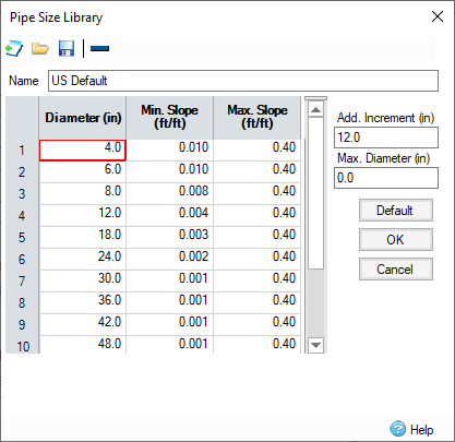
- Select OK to return to the Network Design Wizard.
- In this example project, a design engineer has already laid out the desired invert elevations and slopes of the stormwater pipe network. In order to only size pipe diameters, select Slopes and Invert Elevations
under the Lock Slope Options
drop-down menu. Before continuing uncheck the option to
Allow Manhole Sizing, this means the manholes sizes in the template used will not be changed. Select Next on the
Network Design Wizard to proceed.
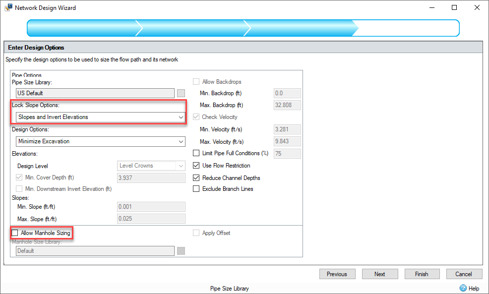
- The
Summary of Changes table lists the changes made to the network, with cells highlighted in orange to indicate the value has changed. By hovering over a highlighted value the previous value can be seen. As the invert elevations and slopes of the pipe network were locked only Diameter changes were made to accommodate incoming flow to the system, based on the Preliminary Sizing Inflow Area parameters and the constraints chosen in the 'Flow Criteria' step of the wizard. Select
Finish to apply updates and review the
Network Design Report.
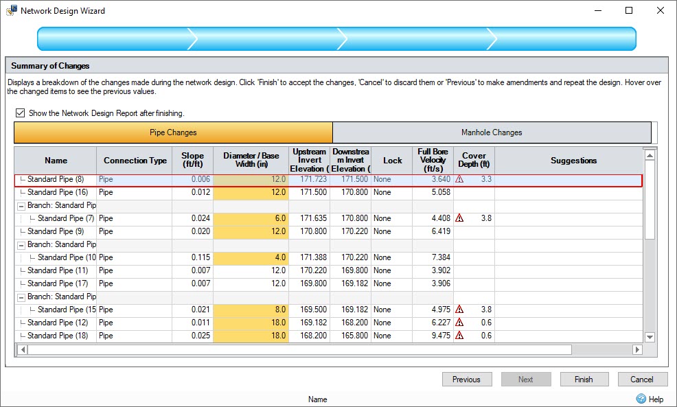
- Upon selecting
Finish for the Network Design Wizard, by default the
Network Design Report will be shown. There are several result formats to choose from, including the standard
HEC-22 Preliminary Sizing Report format. Review the design results as desired and close the dialog when completed. Additional toolbar options exist to change
Network Design Criteria,
Recalculate Rational Results and
Audit changes against Network Design Criteria.
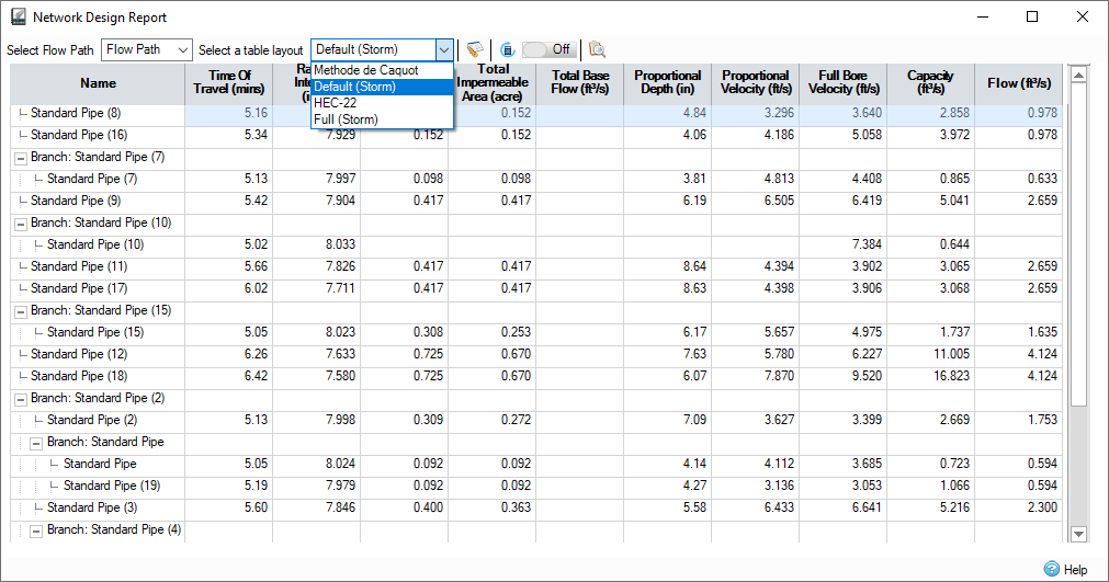
Validate Network Data
- For a system wide check for any potential discrepancies, under the Analysis ribbon select either Validate or Go – this will check the data and list any potential issues in the model.

- When the
Comm (3) Inflow Area was connected to a new destination the original Inlet specification is no longer applicable. Check the Connectivity box and then select Apply to automatic update this item.

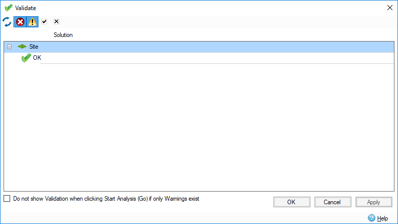
- At this point all inconsistencies between the Junctions and the Connections have been noticed and automatically corrected. The Validate dialog shows no discrepancies are outstanding. Select
OK to close the dialog.
- Now the stormwater system is ready for full hydraulic analysis – browse to the Analysis ribbon and select Go to solve the model.