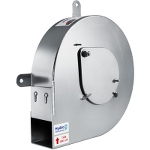
Hydro-Brake® Optimum outlets restrict the flow in surface/storm water or sanitary/combined sewer systems by inducing a vortex flow pattern in the water passing through the device, having the effect of increasing back-pressure.

Their ‘hydrodynamic’ rather than ‘physical restriction’ based operation provides flow regulation whilst maintaining larger clearances than most other types of flow control, making them less susceptible to blockage. Their unique “S”-shaped head-flow characteristic also enables them to pass greater flows at lower heads, which can enable more efficient use of upstream storage facilities.
This document provides guidance relating to the selection and use of Hydro-Brake® Optimum flow controls.
The information provided in this ‘help’ section is intended for the purposes of general guidance only - individual application requirements may differ. If in doubt, or to enquire about new product additions, please contact your local Hydro-Brake® Optimum distributor, details as below
|
Hydro International (Stormwater Division) & HRD Technologies Ltd Shearwater House Clevedon Hall Estate Victoria Road Clevedon BS21 7RD UK
Tel: +44 (0) 1275 337937 (Hydro-Brake® hotline) Tel: +44 (0) 1275 878371 (general enquiries) Fax: +44 (0) 1275 874979
Website: www.hydro-int.com e-mail: enquiries@hydro-int.com
|
© Hydro International Ltd 2019. All rights reserved.
Hydro-Brake® Optimum: Specifications
Invert Elevation - The invert elevation of the control.
Design Depth - The desired design depth of the control (where the vortex is fully initiated). This should be entered as a depth above the invert elevation of the control and will vary between different structures and manholes depending on the depth of storage structure and desired freeboard.
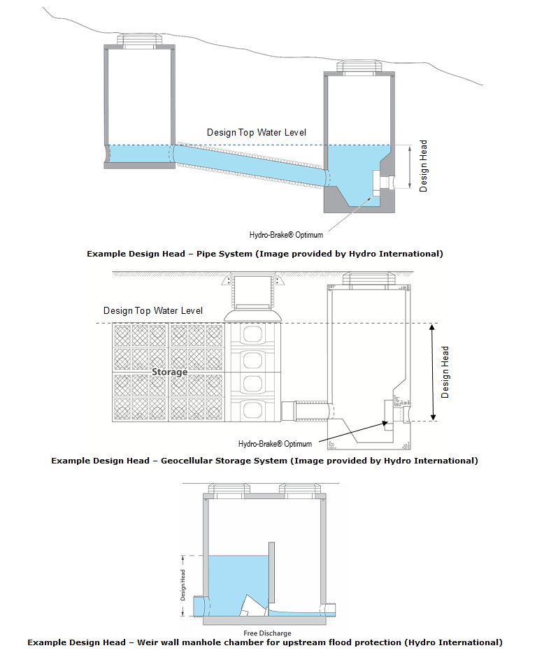
Design Flow - The desired design flow of the control (where the vortex is fully initiated).
Objective - The Hydro-Brake® design objective, see below for further details.
Application - The Hydro-Brake® design application, see Hydraulic Characteristics below for further details.
Sump Available - Indicates whether or not there is the provision of a sump to accommodate the flow control.
Flush Flow - See Hydraulic Characteristics below for further details. If the checkbox is unticked, this defaults to the Design Flow.
Unit Reference - This Unit Reference indicates the model of Hydro-Brake®.
To see a list of possible units, a Calculator is provided:
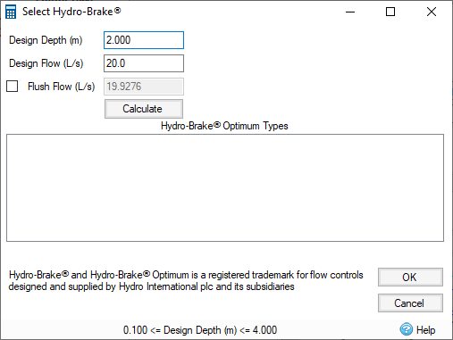
Design Depth, Design Flow, and Flush Flow can be specified as before. Retrieving results via the Calculate button will return the Unit Reference and Outlet Diameter for each Objective.
The most efficient and adaptable Hydro-Brake® for surface water applications, offering engineers the unique ability to precisely tailor the hydraulic response of the device to meet particular design objectives.
The Hydro-Brake® Optimum’s hydraulic performance, structural design, fit for purpose, manufacturing, and quality procedures have been independently verified by the British Board for Agrément (BBA) and the Water Research Council (WRc).


Supported Hydro-Brake® Optimum Ranges & Models:
The Table below provides a summary of the Hydro-Brake® Optimum models supported.
|
Style/Typical Shape |
Application |
Design/Installation Notes |
|
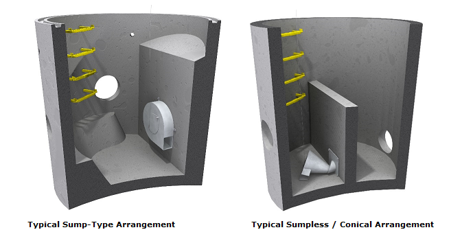
Sump-type
|
Surface/storm water only |
BBA and WRc Approved. Design objective can be specified (see Section 4.1 below) Sump-type units require the provision of a sump to accommodate the flow control. Sump-type units are unsuitable for use in sanitary/combined systems. |
|
Non sump-type
|
Sanitary/combined and surface/storm water |
BBA and WRc Approved. Design objective can be specified (see Section 4.1 below) Non sump-type units do not require the provision of a sump to accommodate the flow control. Instead the unit is benched into the chamber. Non sump-type units are suitable for use in both sanitary/combined systems and surface/stormwater systems. |
Hydraulic Characteristics
Generally all Hydro-Brake® Optimum flow controls should be designed such that the duty/design flow is not exceeded at any point on the head-flow curve.
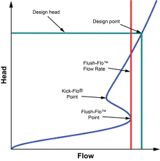
Figure 1: Typical Head Versus Flow Characteristics of Hydro-Brake® Optimum flow controls
The Hydro-Brake® Optimum hydraulic characteristic curve consists of three distinct points, each corresponding to different governing flow control behavior:
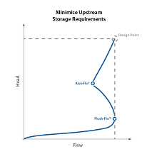
1) Flush Flo™ - The point at which the vortex begins to initiate and have a throttling effect. The red line on the characteristic curve highlights the flow rate at the Flush-Flo™ point (see figure 1 above). This point on the Hydro-Brake® Optimum curve is usually equal to, if not much nearer, to the maximum design flow (Design Point) than other vortex flow controls leading to more water passing through the unit during the earlier stages of a storm, thus reducing the amount of water that needs to be stored upstream.
2) Kick Flo® - The point at which the vortex has fully initiated and at which the curve begins to return back to follow the orifice curve.
3) Design/Duty Point - The desired head / flow condition.
Where a drainage system design has been completed around the use of a particular vortex flow control, the same flow control, or a flow control that has been confirmed to provide equivalent hydraulic performance over the full range of heads, must be used in the final installation.
Calculations within the program are based on a consideration of the full hydraulic characteristic of the flow control, not only the design / duty point. It is essential that the full unit reference / type, diameter (where given), objective (where stated) and control points (where stated) are included on any specification.
Hydro-Brake® Optimum Selection Guidance
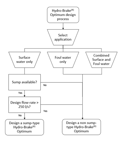
Selection of the most appropriate Hydro-Brake® Optimum Flow Control for a particular application depends on a number of considerations, including the type of sewer system, the hydraulic characteristic of the device, device clearances and overall physical dimensions. The program provides outputs for hydraulic characteristic and outlet size. Depending on the particular application of the Hydro-Brake® Optimum, the appropriate style unit is selected within the flow control design process.
The flow chart below provides information on the Hydro-Brake® Optimum style selection process taking into account the considerations of type of sewer system.
If a Hydro-Brake ® Optimum is not designed:
In the event that a Hydro-Brake® Optimum cannot be designed within the software, this is because the device is outside of the BBA & WRc accreditation ranges. This does not mean a Hydro-Brake® Optimum cannot be supplied, however, some additional information and considerations must be accounted for in the design of the device. Contact Hydro International for further information.
Hydro-Brake® Optimum Design Objective
A unique feature of the Hydro-Brake® Optimum is the ability to manipulate the flush flow, the point at which the vortex forms within the device to allow a fully customized hydraulic response to best suit the site requirements.
The Hydro-Brake® Optimum can be configured to prioritize different hydraulic objectives by tailoring the head-discharge characteristic curve.
1) Minimize storage requirements (default)
Unit Code: SHE/CHE
|
|
This is the default option and will generally result in the smallest volume of upstream storage by aligning the flush flow point with the design point as far as practicable whilst also maximizing the head at the kick flow point. This will pass the greatest possible volume of water downstream during the earlier stages of a storm event thus consistently minimizing upstream storage requirements. |
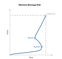
2) Minimize blockage risk
Unit Code: SCL/CCL
|
|
Selecting this option will maximize the inlet and outlet openings of the Hydro-Brake® Optimum unit to maintain the largest possible clearances and minimize the risk of any debris that is being carried within the flow from becoming lodged in the unit. |
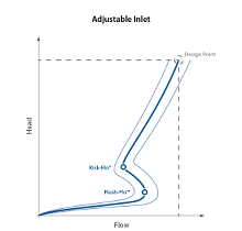
3) Future proof
Unit Code: SCL/CCL
|
|
The addition of an adjustable inlet gate to the Hydro-Brake® Optimum allows the design flow to be adjusted by up to 20% post-installation. Note: Modelling of the range of adjustment is not currently supported in the software. Contact your local distributor to obtain full details.
|
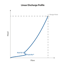
4) Linear Discharge Profile
Unit Code: SCU/CCU
|
|
This option will generate a discharge profile as close to linear as possible, providing similar hydraulic behavior to an orifice plate, but with much greater clearances for reduced blockage risk. |
Calculations within the program are based on a consideration of the full hydraulic characteristic of the flow control, not only the design / duty point. It is essential that the full unit reference / type, diameter (where given), objective (where stated) and control points (where stated) are included on any specification.
Fully dimensioned drawings of all Hydro-Brake® Optimum Flow Controls can be obtained using Hydro International’s online design tool at https://designtools.hydro-int.com or by contacting Hydro International.
