| File/s needed: |
| Click to download the METRIC tutorial model files. |
Flow Paths
Flow Paths are an important consideration in InfoDrainage. Profile Views are shown in terms of Flow Paths. Flow Paths are automatically created when using the Add Network tool or Add Train tool. These paths can also be defined manually by right-clicking the Flow Paths from the Tree View and selecting Add, and then selecting the objects that form the flow path. These can be added individually, or by selecting the US and DS objects only.
- Continue working on your previous file or open Initial Build.iddx.
- Go the the File ribbon, select Save As and save the file as Defining Flow Paths.iddx.
- Click the Select tool on the Toolbox.
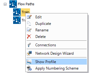
- To view a long section (profile), right-click the Train Flow Path that was automatically created and select Show Profile.
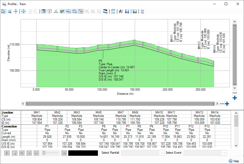
This allows us to navigate a Flow Path and see where the pipe and manhole locations are. It is quite clear that the design is not optimized as there are some pipes that will be flowing upstream. We can use the Network Design Wizard to size pipes and design the network to our default specifications.
- Close the Flow Path profile.
Network Design Wizard
- Go to the Preliminary Sizing Ribbon > Network Design Wizard.

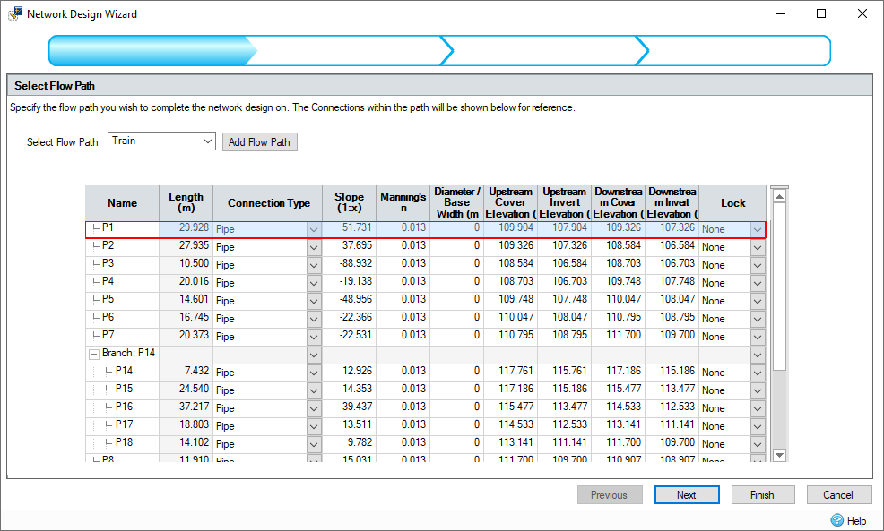
- Make sure the selected flow path is Train and click Next. The branch line will automatically be included in the sizing. If our Flow Profile was not yet specified or needs editing we could use the
Add Flow Path tool to add it from the Plan.
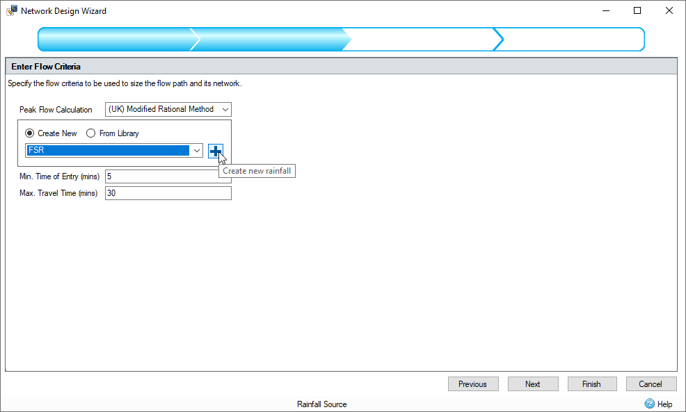
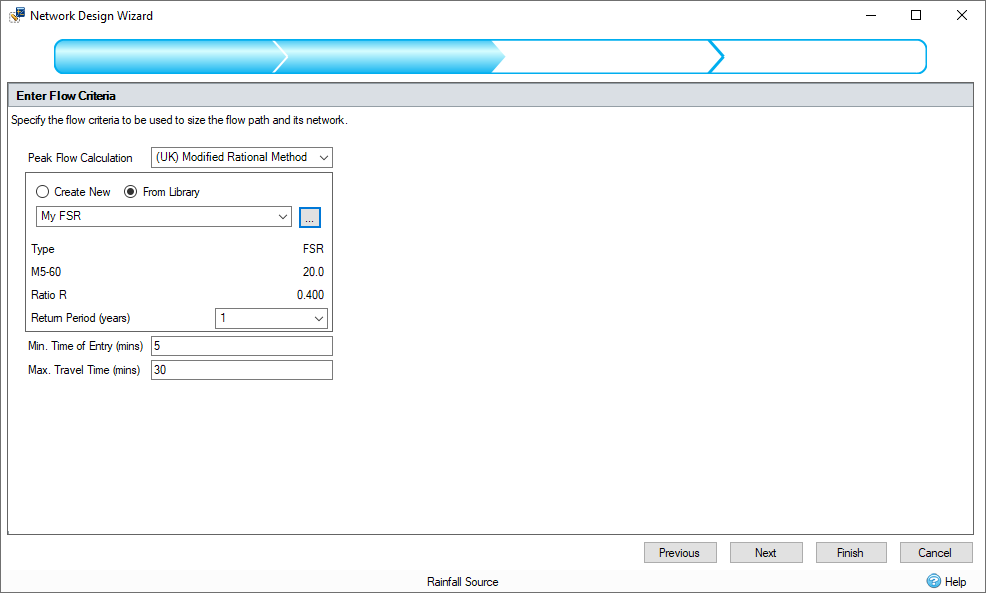
- In Enter Flow Criteria, make sure the Peak Flow Calculation is set to (UK) Modified Rational Method.
- Use the drop-down to select FSR, and then the + create the rainfall data.
- From the Parameters tab, the M5-60 and R can be entered, additionally you can use the map to select rainfall data for a location. Give your data a name (e.g. My FSR), then enter values of 20 for M5-60 and 0.4 for Ratio R. Select both Summer and Winter for Storm Profile.
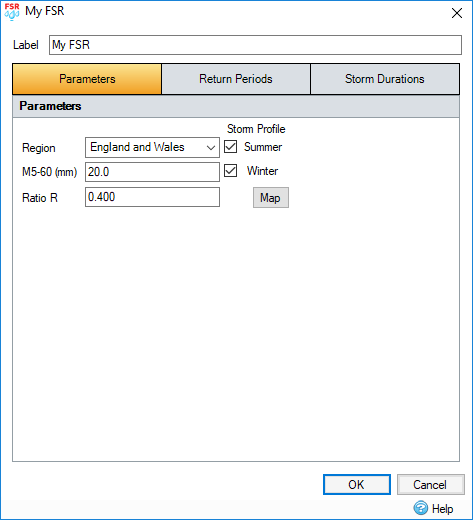
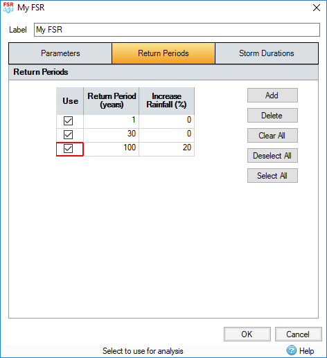
- Click the Return Periods tab. For this example, use a return period of 1, 30 and 100 + 20% Increase Rainfall. Enter the data as below in the appropriate cells and ensure the Use box is checked for all Return Periods.
- Go to the Storm Durations tab and click the Default button. Click OK to close the form and create the rainfall record.

- Check that a Return Period of 1 is selected in the Network Design Wizard. This is the return period we are going to design our pipes to meet the no surcharge criteria. We will use the 30 and 100 year return periods for simulations later on. Click Next.
- The Design Options should be defined as follows. Note that the Design Level has been set to Level Crowns.
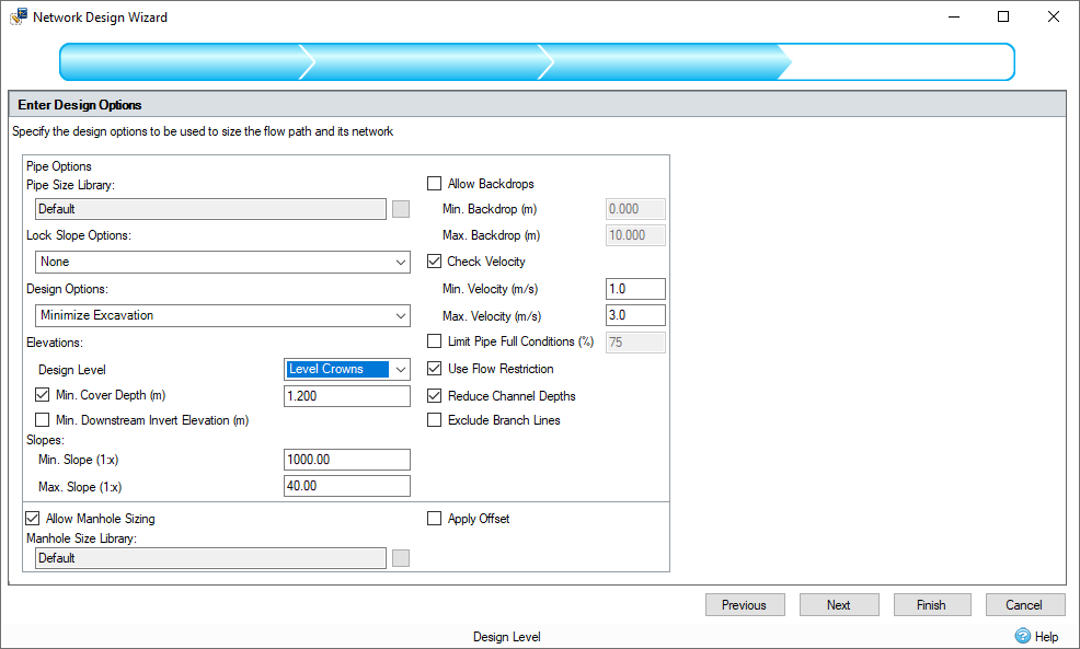
- Click Next. The Network Design Wizard will adjust attributes of the pipes to try and meet our Design Criteria.
- In the Summary of Changes we can review the two tabs to decide if we are happy with the updates made. Orange cells indicate a value has been changed. The previous value can be viewed by hovering over any cell. If values do not meet the design criteria, then a warning triangle will appear next to the value in question, you can hover over these warnings to see which criteria have not been met. For this example, these values that do not meet the criteria are related to slope / velocity because the design is following the surface profile. This is acceptable for the tutorial.

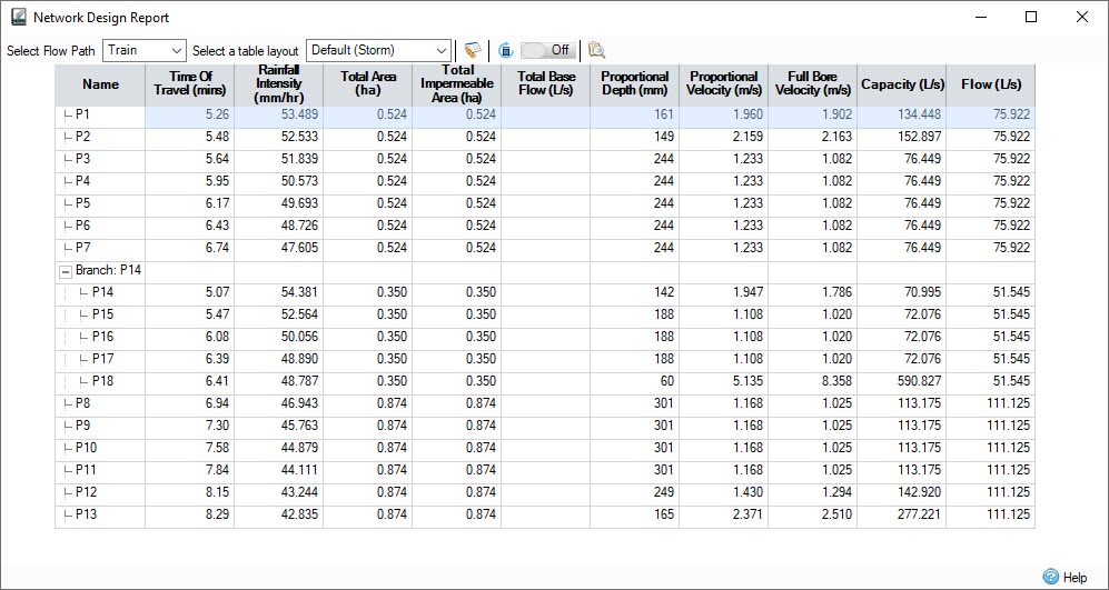
- Click Finish which will apply the changes to the design. The Network Design Report is shown after the wizard. This gives us information about the pipes that have been sized. Network Design Wizard optimizes the network for a no surcharge criteria for the selected rainfall, this is evident in the connection window as pipe flow is less than capacity. There are buttons at the top of the report to Recalculate Rational Results or Audit against the Network Design Criteria if anything changes without having to rerun the wizard.
- Close the Network Design Report dialog.
- In the Tree View, double-click the Train flow path to show the profile and see how the design has been revised.
- Save the model.