Tank stormwater controls may be used to model a range of stormwater controls including, but not limited to, tanks and municipal harvesting tanks.
Total Volume
The Total Volume value shown in the bottom-right corner of the data form shows the volume available in the system up to the Freeboard Elevation.
Dimensions
The Dimensions tab has the following fields:

The depth within the stormwater control is determined from two of the following three parameters, with the third automatically calculated based on the option selected:
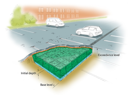
- Exceedance Elevation - Represents the elevation (above datum) of the stormwater control above which flooding is reported. This may be the elevation that interacts with the ground surface or the top of an embankment, whichever is higher. An overflow or spillway crest elevation may be specified at a lower elevation as part of the outlet control details. If a Surface Data model (TIN) is present the Exceedance elevation will automatically be picked up from the center of the icon or from the lowest point on the bioretention perimeter if an area has been drawn. This combined with the Freeboard setting allows a Status of Flood Risk to be assigned to the system on the Summary. For stormwater controls on a slope the Exceedance Elevation applies to the downstream (lowest) end. Above the Exceedance Elevation, water will be stored above the ground and then allowed to drain back into the network. The ponding area used for the flooded volume is the area the Tank occupies on the plan.
- Depth - Represents the depth of the stormwater control.
- Base Elevation - Represents the elevation (above datum) of the base of the stormwater control.
Freeboard - Controls how close to the specified Exceedance elevation the water must reach before the Status (on the Summary) shows Flood Risk.
Initial Depth - Defines the initial wetted depth within the facility.
Porosity - Defines the percentage of the tank that is available for storage. This is dictated by the type of fill material that is used, i.e. 100% if empty or typically 30% for rubble.
Average Slope - The average side slope is determined from the difference in the Top Area and Base area, assuming circular sides.
Depth-Area-Volume Spreadsheet
This spreadsheet specifies the circular infiltration cross-sectional area and volume for the structure at each depth. A depth of 0m corresponds to the invert elevation and area specified at 0m is considered to be the base of the structure. All areas above the top of the structure may be left as blank.
Above the spreadsheet is an Editable Column drop-down list box which allows the user to specify either 'Area' or 'Volume' values in the spreadsheet.
Whilst the Area at each depth specifies the circular cross-sectional area at that depth, the volume is the cumulative volume for all depths up to the depth the next row. If the Editable Column drop-down list box is 'Area' then the user can specify an area and the volume in the same row is calculated calculated. Conversely if 'Volume' is selected in the Editable Column drop-down list box then the user can specify a volume in a row and the area is calculated in the subsequent row (keeping the area in the same row the same). Note that in this case it is possible to specify a volume that is it too small for the area of the current row and height between the current and next rows, in which case the area will be set to -1 and a higher volume will need to be specified.
Depth Increment (m)
Enter the depth increment for the tank area spreadsheet. Small values lead to a more accurate result but limit the height of the structure.
Sizing Calculator

The Sizing Calculator option allows the user to re-size the Tank by specifying a volume and a parameter to modify to achieve that volume. It also allows the user to specify a Side Slope for the Tank. The Sizing Calculator is discussed in more detail in the Stormwater Control Sizing Calculator .
Inlets
Explore the Inlets page for more details on the different types of Inlets that can be specified.
Outlets
Explore the Outlets page for more details on the different types of Outlets that can be specified.
Advanced
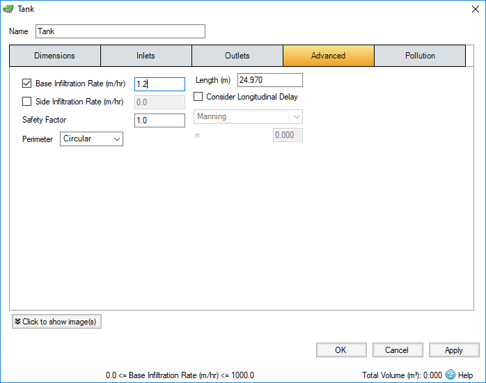
The Advanced tab has the following fields:

Base Infiltration Rate - Defines the rate of infiltration through the base of the filter area. This should be determined from a performance site test.
Side Infiltration Rate - Defines the rate of infiltration through the sides of the filter area. This should be determined from a performance site test.
Safety Factor - Reduces the infiltration rate during the analysis to account for silting up or poor maintenance. This is required for the UK.
Perimeter - Specified whether the perimeter shape for the side infiltration calculation is to be circular or square. The default is circular.
Length - The maximum path length through the stormwater control, used only for the purpose of calculating Time of Travel. The Length will be automatically set from the dimensions of the stormwater control unless over typed, in which case it is set to "user specified ".
Consider Longitudinal Delay - Determines if a time of travel needs to be considered across the structure. This may not be required as they are laid flat and can be considered as filling instantaneously. If the travel time is to be considered a roughness method and value should be selected.
Friction Scheme - Specifies the formula used to calculate velocity and time of travel. Select from: Manning's, and Colebrook-White. The variable below the combo box depends on the option selected.
n - Manning’s n roughness value. Used by the Manning Formula equation to calculate the velocity and therefore time of travel when using the Manning's option.
Roughness - Colebrook-White roughness value. Used by the Colebrook-White Formula equation to calculate the velocity and therefore time of travel when using the Colebrook-White option.
Pollution
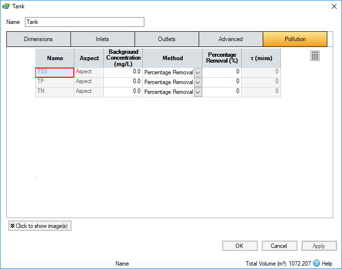
The Pollution tab has the following fields:

Name - Name of pollutants. This is populated based on the Pollutants set up as part of the Site Data.
Background Concentration - Value below which the pollution concentration cannot fall during analysis. When concentration reaches this elevation, no further removal occurs.
Method - Percentage Removal or First Order Decay method can be chosen. Click on the links for more information about each method.
Percentage Removal - Available if Percentage Removal entered. The value entered will be deducted from the Inflow into the system.
τ - The decay time constant or (mean) lifetime of the pollutant. It can be entered manually or calculated from the decay constant or decay half-life. See Pollutant Removal Method - First Order Decay for more details.
