There are devices in InfoSurge that will help to reduce the magnitude of the pressure waves when a transient occurs in the system. These devices are created by first creating a node and then changing it into a Surge Protection Device by clicking on the Surge Protection Device
 (SPD) button. The dialog box will appear that will allow you to select the type of Surge Protection Device that you wish to create. The options are:
Side Discharge Orifice
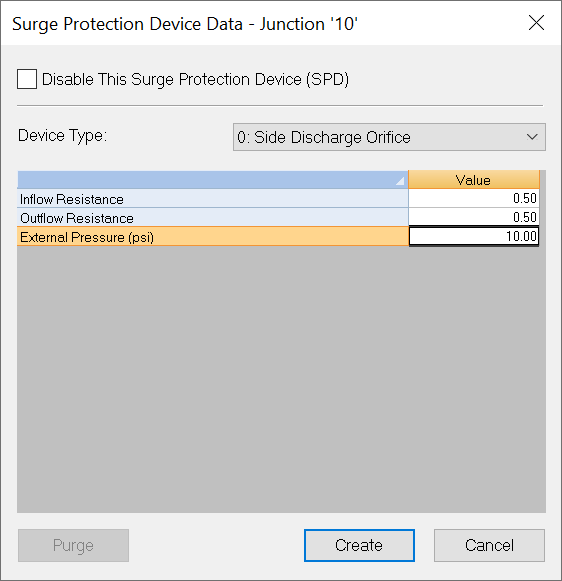
A Side Discharge Orifice (SDO) represents an orifice in the pipeline where flow enters or exits the pipeline based on the pressure at that location. The orifice can discharge into the atmosphere, a fixed head region, or an open or closed surge tank. Applications include valve venting to atmosphere or fixed head region, blow off valve, line rupture, and flow exit through any resistive device into a constant head region. The inflow and outflow resistances can be different (inflow refers to flow into the pipeline and outflow is out of the pipeline). This device also is an integral part of a number of surge control devices including open and closed surge tanks, feed tanks, pressure relief valves, air release (vacuum) valves, and surge anticipation valves.
Disable This Surge Protection Device
If this box is checked, then the selected SPD will not be modeled in the Surge analysis.
Device Type
Type of Surge Protection Device to be used.
Side Discharge Orifice Input Data
-
Inflow Resistance - This specifies the amount of resistance to flow into the system (pipe).
-
Outflow Resistance - This specifies the amount of resistance to flow out of the system (pipe).
-
External Pressure - This field is the external pressure next to the pipe. A value of 0 means exiting to the atmosphere. The Pressure unit is set in the Simulation Options.
Purge - Use the Purge button to remove existing Data.
Create/Update - Enter new or changed data and exit the dialog box window.
Cancel - Cancels any new or changed data and closes the dialog box window.
Open Surge Tank
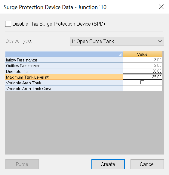
An Open Surge Tank (Spilling Tank and One Way Feed tank) models an open surge tank including a spilling surge tank where the maximum level is specified and a one way open surge tank which allow flow only from the tank into the pipeline and requires a check valve to be defined. The open surge tank is normally used to prevent excessive surges and/or cavitation in regions with low static heads. A feed tank is normally used to prevent cavitation in higher head region.
Disable This Surge Protection Device
If this box is checked, then the selected SPD will not be modeled in the Surge analysis.
Device Type
Type of Surge Protection Device to be used.
Open Surge Tank Input Data
-
Inflow Resistance - This specifies the amount of resistance to flow into the system (pipe).
-
Outflow Resistance - This specifies the amount of resistance to flow out of the system (pipe).
-
Diameter - This is the diameter (m in SI/ ft in English) of the tank.
-
Maximum Tank Level - The maximum level of water [m in SI/ ft in English] in the tank before spillage occurs.
-
Variable Area Tank - When the option is checked off, the surge tank is cylindrical; otherwise, the surge tank has a variable area cross section and a Variable Area Tank Curve is required. Note that Diameter is not required for the Variable Area Tanks.
-
Variable Area Tank Curve - Enter the ID of a curve that represents the Variable Area Tank.
Purge - Use the Purge button to remove existing Data.
Create/Update - Enter new or changed data and exit the dialog box window.
Cancel - Cancels any new or changed data and closes the dialog box window.
One Way Surge Tank
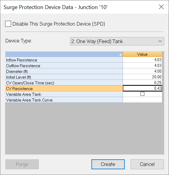
A One Way Surge Tank is an open surge tank that is equipped with a check valve at the entrance which prevents flow from entering the tank. This is useful for controlling down surges at a point where the static head is large and a normal open surge tank would not be practical.
Disable This Surge Protection Device
If this box is checked, then the selected SPD will not be modeled in the Surge analysis.
Device Type
Type of Surge Protection Device to be used.
One Way Feed Tank Input Data
-
Inflow Resistance - This specifies the amount of resistance to flow into the system (pipe).
-
Outflow Resistance - This specifies the amount of resistance to flow out of the system (pipe).
-
Diameter - This is the diameter (m in SI/ ft in English) of the tank.
-
Initial Tank Level - The initial level of water [m in SI/ ft in English] in the tank. Since there is a check valve installed in the connection line, the level in this tank will not go above this level.
-
CV Open/Close Time - This is the amount of time in seconds that it takes for the check valve to go from fully opened to fully closed.
-
CV Resistance - Wide open resistance for the check valve.
-
Variable Area Tank - When the option is checked off, the surge tank is cylindrical; otherwise, the surge tank has a variable area cross section and a Variable Area Tank Curve is required. Note that Diameter is not required for the Variable Area Tanks.
-
Variable Area Tank Curve - Enter the ID of a curve that represents the Variable Area Tank.
Purge - Use the Purge button to remove existing Data.
Create/Update - Enter new or changed data and exit the dialog box window.
Cancel - Cancels any new or changed data and closes the dialog box window.
Closed Surge Tank
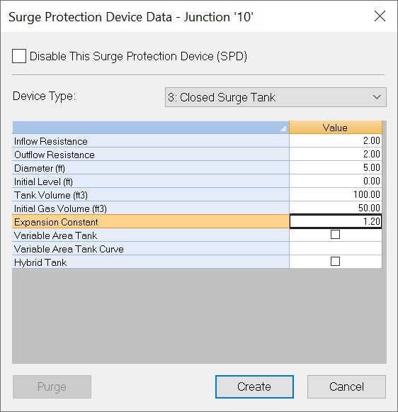
A Closed Surge Tank contains a specified initial gas volume and this air volume will be initially pressurized (using a compressor) to the starting pressure as determined by the initial steady-state analysis. It is normally used to prevent excessive surge and/or cavitation in regions with high static heads.
Disable This Surge Protection Device
If this box is checked, then the selected SPD will not be modeled in the Surge analysis.
Device Type
Type of Surge Protection Device to be used.
Closed Surge Tank Input Data
-
Inflow Resistance - This specifies the amount of resistance to flow into the system (pipe).
-
Outflow Resistance - This specifies the amount of resistance to flow out of the system (pipe).
-
Diameter - This is the diameter of the surge tank. If the diameter field is blank, a fairly large value is assumed.
-
Initial Level - The initial level of water in the surge tank, is based on the junction's elevation. In other words, the initial level is the surge tank water level plus the elevation difference between tank bottom and junction elevation.
-
Tank Volume - This is the volume (m 3 in SI/ ft 3 in English) of the bladder for the tank.
-
Initial Gas Volume - This is the volume [m 3 in SI/ ft 3 in English] of gas present in the tank. The pressure of the gas will be determined by the initial steady state analysis.
-
Expansion Constant - This is the expansion constant for the gas that is used to fill the bladder. This value should be between 1 and 1.4. A value of 1 is used for isothermal compression (no temperature change) and 1.4 is used for adiabatic (temperature change present). In general, if you do not know this value, use 1.2. This data can be obtained from the tank manufacturer.
-
Variable Area Tank - When the option is checked off, the surge tank is cylindrical; otherwise, the surge tank has a variable area cross section and a Variable Are Tank Curve is required. Note that diameter is not required for the Variable Area Tanks.
-
Variable Area Tank Curve - Enter the ID of a curve that represents the Variable Area Tank
-
Hybrid Tank - When the option is checked on, the surge tank is modeled as a Hybrid Tank.
Purge - Use the Purge button to remove existing Data.
Create/Update - Enter new or changed data and exit the dialog box window.
Cancel - Cancels any new or changed data and closes the dialog box window.
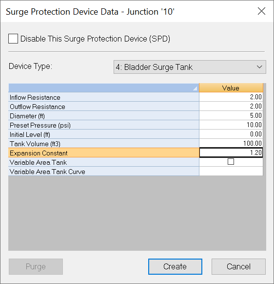
Bladder Surge Tank
Bladder Surge Tank – The pre-set pressure (Ps) is the initial pressure in the bladder prior to opening the valve connecting the tank to the pipeline. At any pipe pressure lower than the Pre-set pressure the bladder fills the tank and there is no flow into or out of the pipeline. This is an undesirable condition. The initial gas volume (Vi) is determined by InfoSurge using the initial line pressure (Pi) at the location of the bladder tank. This gas volume is calculated assuming isothermal compression (PiVi = PsVb). For example, for the data displayed above if the initial line pressure at the 50 cubic foot Bladder Tank is 80 psi, the initial gas volume is Vi = (Pa + Ps) x 50/(80 + Pa) = 13 cubic feet. Here, Pa is atmospheric pressure (14.7 psi).
Disable This Surge Protection Device
If this box is checked, then the selected SPD will not be modeled in the Surge analysis.
Device Type
Type of Surge Protection Device to be used.
Bladder Surge Tank Input Data
-
Inflow Resistance - This specifies the amount of resistance to flow into the system (pipe).
-
Outflow Resistance - This specifies the amount of resistance to flow out of the system (pipe).
-
Diameter - This is the diameter of the surge tank.
-
Preset Pressure - This is the value that the pressure in the connecting pipe must exceed in order for this device to operate. Pressure units are determined by the units selected in the Simulation Options.
-
Initial Level - The initial level of water in the surge tank. The default is zero.
-
Tank Volume - This is the volume (m 3 in SI/ ft 3 in English) of the bladder for the tank.
-
Expansion Constant - This is the expansion constant for the gas that is used to fill the bladder. This value should be between 1 and 1.4. A value of 1 is used for isothermal compression (no temperature change) and 1.4 is used for adiabatic (temperature change present). In general, if you do not know this value, use 1.2. This data can be obtained from the tank manufacturer.
-
Variable Area Tank - When the option is checked off, the surge tank is cylindrical; otherwise, the surge tank has a variable area cross section and a Variable Area Tank Curve is required. Note that Diameter is not required for the Variable Area Tank.
-
Variable Area Tank Curve - Enter the ID of a curve that represents the Variable Area Tank.
Purge - Use the Purge button to remove existing Data.
Create/Update - Enter new or changed data and exit the dialog box window.
Cancel - Cancels any new or changed data and closes the dialog box window.
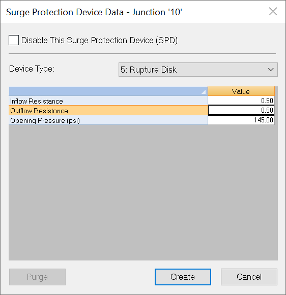
Rupture Disk
A Rupture Disk opens very quickly when the pressure exceeds the opening pressure. A rupture disk is used as a protection device to prevent over-pressurizing a vessel or component. Note that this device functions the same as a cork popping from a hole in a pipe and, once activated, will not reset during the simulation.
Disable This Surge Protection Device
If this box is checked, then the selected SPD will not be modeled in the Surge analysis.
Device Type
Type of Surge Protection Device to be used.
Rupture Disk Input Data
-
Inflow Resistance - This specifies the amount of resistance to flow into the system (pipe).
-
Outflow Resistance - This specifies the amount of resistance to flow out of the system (pipe).
-
Opening Pressure - This is the pressure at the sensing node at which the valve will open. The Pressure unit is set in the Simulation Options.
Purge - Use the Purge button to remove existing Data.
Create/Update - Enter new or changed data and exit the dialog box window.
Cancel - Cancels any new or changed data and closes the dialog box window.
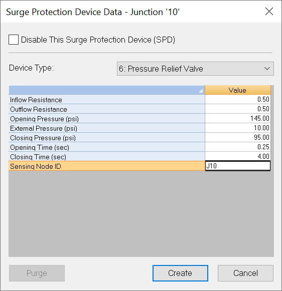
Pressure Relief Valve
A Pressure Relief Valve begins to open when the pressure at the sensing node exceeds the opening pressure. The opening time is the response time for the valve to go from the start to the fully open position. The valve closure is initiated when the pressure (head) drops below the closing pressure. Because of pressure fluctuation at the sensing node, this valve can remain open for longer periods. If the valve exits to a pressurized region (e.g., a tank) the External Pressure should be specified. The pressure to activate the valve is generally sensed at the valve but any node can be used for this purpose. A pressure relief valve is normally used to prevent excessive pressure surge by venting liquid.
Disable This Surge Protection Device
If this box is checked, then the selected SPD will not be modeled in the Surge analysis.
Device Type
Type of Surge Protection Device to be used.
Pressure Relief Valve Input Data
-
Inflow Resistance - This specifies the amount of resistance to flow into the system (pipe).
-
Outflow Resistance - This specifies the amount of resistance to flow out of the system (pipe).
-
Opening Pressure - This is the pressure at the sensing node at which the valve will open. The Pressure unit is set in the Simulation Options.
-
External Pressure - This field is the external pressure next to the pipe. A value of 0 means exiting to the atmosphere. The Pressure unit is set in the Simulation Options.
-
Closing Pressure - When the valve is open, this is the pressure at the sensing node that will cause the valve to close. The Pressure unit is set in the Simulation Options.
-
Opening Time - This is the time in seconds that the valve takes to fully open.
-
Closing Time - This is the time in seconds that the valve takes to fully close.
-
Sensing Node ID - This is the location of the node where the sensor for the PRV is installed.
Purge - Use the Purge button to remove existing Data.
Create/Update - Enter new or changed data and exit the dialog box window.
Cancel - Cancels any new or changed data and closes the dialog box window.
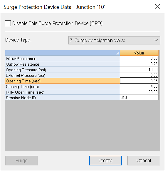
Surge Anticipation Valve
A Surge Anticipation Valve activates on a down surge when the pressure at the sensing node drops below the opening pressure. After opening is initiated the surge anticipation valve completes a cycle where it opens fully in the opening time, remains fully open for the fully open time and closes completely in the closing time. If the valve exits to a pressurized region (e.g., a tank) the External Pressure should be specified. The pressure to activate the valve is generally sensed at the valve but any node can be used for this purpose.
Disable This Surge Protection Device
If this box is checked, then the selected SPD will not be modeled in the Surge analysis.
Device Type
Type of Surge Protection Device to be used.
Surge Anticipation Valve Input Data
-
Inflow Resistance - This specifies the amount of resistance to flow into the system (pipe).
-
Outflow Resistance - This specifies the amount of resistance to flow out of the system (pipe).
-
External Pressure - This field is the external pressure next to the pipe. A value of 0 means exiting to the atmosphere. The Pressure unit is set in the Simulation Options.
-
Opening Time - This is the time in seconds that the valve takes to fully open.
-
Closing Time - This is the time in seconds that the valve takes to fully close.
-
Fully Open Time - The amount of time that the valve stays fully open once activated.
-
Sensing Node ID - This is the location of the node where the sensor for the PRV is installed.
Purge - Use the Purge button to remove existing Data.
Create/Update - Enter new or changed data and exit the dialog box window.
Cancel - Cancels any new or changed data and closes the dialog box window.
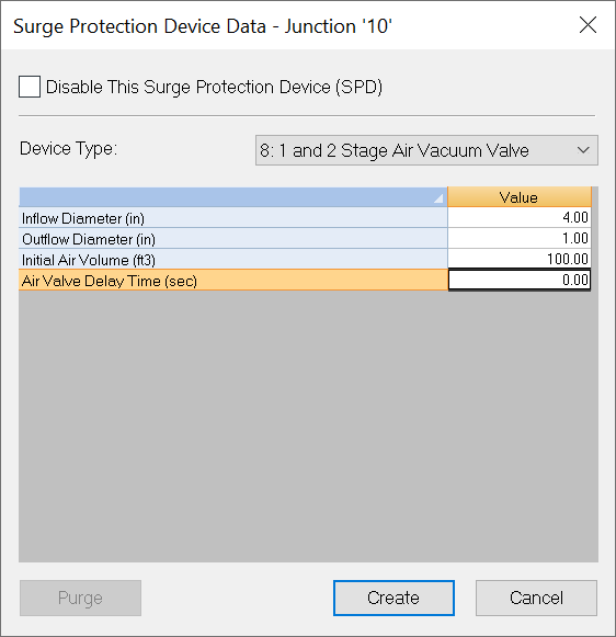
1 and 2 Stage Air Vacuum Valve
A Single Stage Air Vacuum Valve takes air in when the pipeline pressure drops below atmospheric and releases air to the atmosphere when the pipeline pressure exceeds atmospheric pressure. The single stage air valve has the same size orifice for inflow and outflow (usually the same orifice). Also an initial volume of air can be specified to model startup with air in the system at the air valve location.
A Two-Stage Air Valve has a different size orifice for inflow and outflow. The outflow orifice is smaller to reduce the rate of air expulsion and the "air slam" which occurs when all the air is expelled and the liquid columns rejoin. See Air Slam Pressure Calculator to calculate the Air Slam Pressure.
Disable This Surge Protection Device
If this box is checked, then this surge protection device (SPD) will not be modeled in the current Surge analysis.
Device Type
Select the type of Surge Protection Device to be used.
1 & 2 Stage Air Vacuum Valve Input Data
-
Inflow Diameter - The diameter (mm in SI/ inch in English) of the orifice that allows air to enter the system.
-
Outflow Diameter - The diameter of the orifice (mm in SI/ inch in English) that allows air to exit the system. (For 1 stage air valves, the Inflow and Outflow diameters will be the same).
-
Initial Air Volume - This allows you to specify an air pocket volume [m 3 in SI/ ft 3 in English] that has accumulated at the valve at the start of the simulation. Normally this value is 0 which means that no air pocket is initially present.
-
Air Valve Delay Time - Air Valve Delay Time is the time for the air valve to activate.
Purge - Use the Purge button to remove existing Data.
Create/Update - Enter new or changed data and exit the dialog window.
Cancel - Cancels any new or changed data and closes the dialog window.
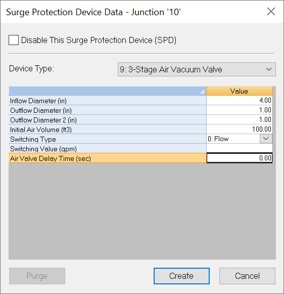
3 Stage Air Vacuum Valve
A Three-Stage Air Valve is a device with 3 orifices, one that allows air in and two that allow air out. The first outlet orifice is large to allow most of the air to be expelled quickly and the second outflow orifice is smaller to release the air more slowly and reduces "air slam". The transition from the primary outflow orifice (Outflow Diameter) to the second orifice (Outflow Diameter 2) usually occurs at a specified pressure (psi or kpa) but can be modeled to switch on flow (cfs or cms) or volume (ft^3 or m^3). These devices are usually constructed so that a "float" controls which orifice is activated.
Disable This Surge Protection Device
If this box is checked, then the selected SPD will not be modeled in the Surge analysis.
Device Type
Type of Surge Protection Device to be used.
3-Stage Air Vacuum Valve Input
-
Inflow Diameter - The diameter (mm in SI/ inch in English) of the orifice that allows air to enter the system.
-
Outflow Diameter - The diameter of the orifice (mm in SI/ inch in English) that allows air to exit the system. (For 1 stage air valves, the Inflow and Outflow diameters will be the same).
-
Outflow Diameter 2 - The diameter of the secondary orifice (mm in SI/ inch in English) that will be utilized for outflow if the flow, pressure or air volume exceeds the corresponding switching value.
-
Initial Air Volume - This allows you to specify an air pocket volume [m 3 in SI/ ft 3 in English] that has accumulated at the valve at the start of the simulation. Normally this value is 0 which means that no air pocket is initially present.
-
Switching Type - This setting determines if the switch value is a Volume, Flow, or Pressure.
-
Switching Value - This is the value at which the 2nd outflow orifice will be activated. In case of Flow or Pressure as a switching type, the unit is set by the Flow and Pressure units selected in the Simulation Options. In case of Volume, the unit is m 3 in SI or ft 3 in English.
-
Air Valve Delay Time - Air Valve Delay Time is the time for the air valve to activate.
Purge - Use the Purge button to remove existing Data.
Create/Update - Enter new or changed data and exit the dialog box window.
Cancel - Cancels any new or changed data and closes the dialog box window.
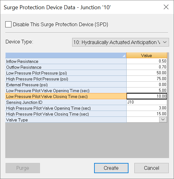
Hydraulically Actuated Anticipation Valve
A Hydraulically Actuated Anticipation Valve (Hyd-SAV) is a surge anticipation valve that is controlled by pressures rather than time. It can model both Low Pressure Pilot (LPP), which operates during downsurge, and High Pressure Pilot (HPP), which operates during upsurge.
Disable This Surge Protection Device
If this box is checked, then the selected SPD will not be modeled in the Surge analysis.
Device Type
Type of Surge Protection Device to be used.
Hydraulically Actuated Anticipation Valve Input Data
-
Inflow Resistance - This specifies the amount of resistance to flow into the system (pipe).
-
Outflow Resistance - This specifies the amount of resistance to flow out of the system (pipe).
-
Low Pressure Pilot Pressure - Pressure setting for Low Pressure Pilot.
-
High Pressure Pilot Pressure - Pressure setting for High Pressure Pilot.
-
External Pressure - This field is the external pressure next to the pipe. A value of 0 means exiting to the atmosphere.
-
Low Pressure Pilot Valve Opening Time - Time for Low Pressure Pilot open Surge Anticipation Valve from closed to fully open.
-
Low Pressure Pilot Valve Closing Time - Time for Low Pressure Pilot open Surge Anticipation Valve from fully open to closed.
-
Sensing Junction ID - This is the location of the node where the sensor is installed. If left blank, the junction with Surge Anticipation Valve is the sensing junction.
-
High Pressure Pilot Valve Opening Time - Time for Low Pressure Pilot open Surge Anticipation Valve from closed to fully open.
-
High Pressure Pilot Valve Closing Time - Time for High Pressure Pilot open Surge Anticipation Valve from fully open to closed.
-
Valve Type - This specifies the valve type of Surge Anticipation Valve.
Purge - Use the Purge button to remove existing Data.
Create/Update - Enter new or changed data and exit the dialog box window.
Cancel - Cancels any new or changed data and closes the dialog box window.
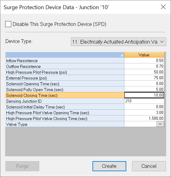
Electrically Actuated Anticipation Valve
A Electrically Actuated Anticipation Valve (Elec-SAV) is a combination of regular SAV and Hyd-SAV, and requires one additional data item called Delay Time. It starts opening on pump trip condition (actuated by a solenoid), gets to stay open for a specified time period, and closes thereafter. HPP opens the valve during upsurge when the pressure at the sensing node rises above the preset pressure and keeps the valve open until the pressure drops below the preset pressure.
Disable This Surge Protection Device
If this box is checked, then the selected SPD will not be modeled in the Surge analysis.
Device Type
Type of Surge Protection Device to be used.
Electrically Actuated Anticipation Valve Input Data
-
Inflow Resistance - This specifies the amount of resistance to flow into the system (pipe).
-
Outflow Resistance - This specifies the amount of resistance to flow out of the system (pipe).
-
High Pressure Pilot Pressure - Pressure setting for High Pressure Pilot.
-
External Pressure - This field is the external pressure next to the pipe. A value of 0 means exiting to the atmosphere.
-
Solenoid Opening Time - Time for Surge Anticipation Valve to go from closed to fully open during down surge.
-
Solenoid Fully Open Time - Time for Surge Anticipation Valve to stay in fully open mode during down surge.
-
Solenoid Closing Time - Time for Surge Anticipation Valve to go from fully open to closed during down surge.
-
Sensing Junction ID - This is the location of the node where the sensor is installed. If left blank, the junction with Surge Anticipation Valve is the sensing junction.
-
Solenoid Initial Delay Time - Time for Surge Anticipation Valve to activate.
-
High Pressure Pilot Valve Opening Time - Time for Low Pressure Pilot open Surge Anticipation Valve from closed to fully open.
-
High Pressure Pilot Valve Closing Time - Time for High Pressure Pilot open Surge Anticipation Valve from fully open to closed.
-
Valve Type - This specifies the valve type of Surge Anticipation Valve.
Purge - Use the Purge button to remove existing Data.
Create/Update - Enter new or changed data and exit the dialog box window.
Cancel - Cancels any new or changed data and closes the dialog box window.
Note 1. If you have a junction node selected but the Surge Protection Device
![]() button is disabled, then a demand change curve has already been defined for this node. In order to change the node to a Surge Protection Device, you will need to click on Demand Change button and then click Purge in the Junction Demand Change window. The Surge Protection Device
button is disabled, then a demand change curve has already been defined for this node. In order to change the node to a Surge Protection Device, you will need to click on Demand Change button and then click Purge in the Junction Demand Change window. The Surge Protection Device
![]() button will now be enabled.
button will now be enabled.
Note 2. A surge protection device should be located in a junction connected between two pipes only. If the device is placed on another junction (e.g., with a one or three pipe connections), InfoSurge will create the error message: “invalid pipe connection configuration at surge protection device.”