The Quick-Start tutorial is designed for first-time users of InfoWater Pro Skeletonizer and provides a guided tour to core commands and functions used to create and execute a network segmentation (reduction) run (RST application). The Quick Start tutorial will help you become familiar with the core set of InfoWater Pro Skeletonizer features and should be used as a launching point to a more comprehensive understanding of the program. The estimated time to complete the Quick Start tutorial is approximately 15 minutes. The Quick Start tutorial will help you become familiar with the following network segmentation applications:
- Initiate a network trimming application
- Execute a network reduction application
- Perform a network skeletonization application
During the Quick Start tutorial, you will modify a project called “SampleSeg”. This project can be downloaded from Quick Start Tutorial Example files. Once you go to the Examples directory, search for the SampleSeg.aprx file (see below). Click on the file to open your SampleSeg.aprx file in ArcGIS Pro.
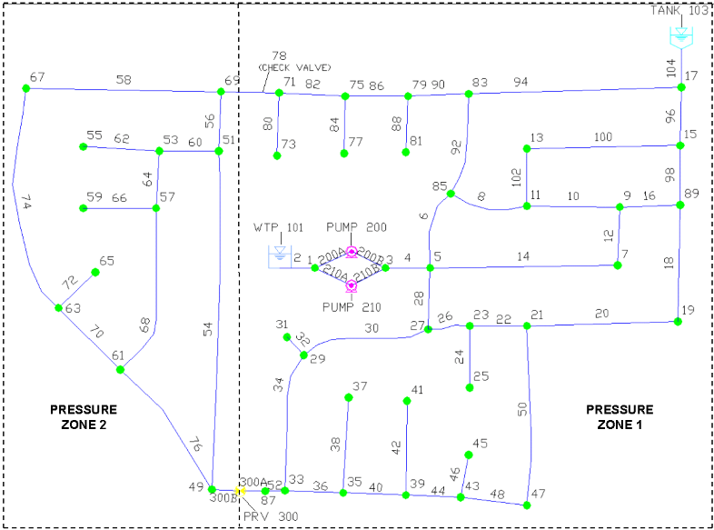
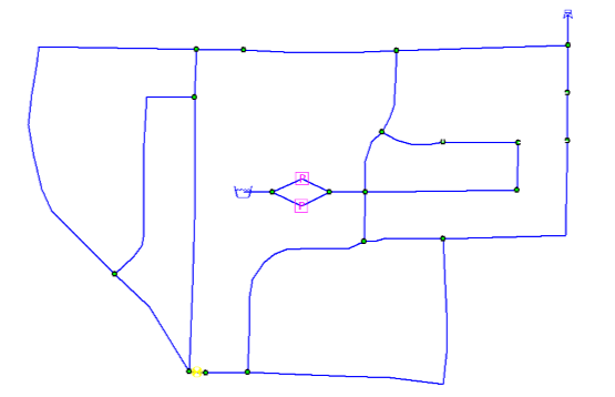
 The SampleSeg project modified in this tutorial illustrates how InfoWater Pro Skeletonizer automatically performs RST applications to remove excessive pipe segments and reduce large, detailed network models to a manageable size ready for analysis. The SampleSeg model schematic is shown below. The completed model contains two pressure zones and consists of the following components:
- One reservoir (storage node 101)
- One tank (storage node 103)
- Two pumps located at the water treatment plant and numbered 200 and 210
- One pressure reducing valve located at node 300
- One check valve located in pipe 78
- Fifty-eight pipes
- Forty-five junction nodes
- Total system demand of 707 gpm
Pump 200 turns off when the level in tank 103 rises above 40 feet and turns on when the level in tank 103 falls below 25 feet. Pump 210 turns off when the level in tank 103 rises above 45 feet and turns on when the level in tank 103 falls below 35 feet.
Step 1: Open the SampleSeg Project
The first step is to open the InfoWater Pro project.
- From the Start menu, select Programs, choose the InfoWater Pro program group, and then select InfoWater Pro. This will load InfoWater Pro or go to your Examples directory and click on your SampleSet.aprx file.
- Choose
Open from the
File menu. On the
Specify an Existing InfoWater Pro Project File dialog box, navigate to the directory containing the
SampleSeg project and choose that InfoWater Pro project (SampleSeg.aprx).
Note: If you have not previously downloaded the Example files, you can do so from Quick Start Tutorial Example files.
- Before continuing, save the SampleSeg project to a new project. If you wish to restart the tutorial, the original project will be available. Choose the Save As command from the File menu. On the dialog box, enter the new project name “Tutorial”. This becomes the active project.
- From the
InfoWater Pro ribbon, choose the
Apps
 button. With the
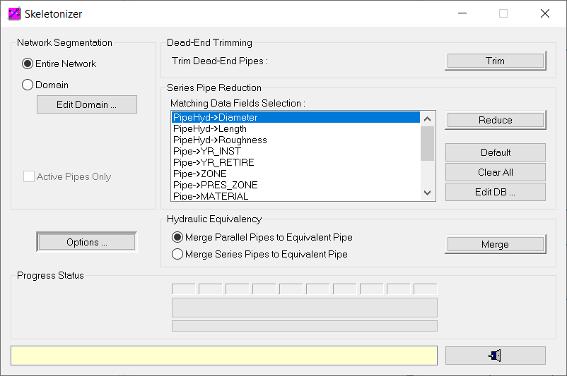
Apps Manager dialog box open, select InfoWater Pro Skeletonizer from the list of applications and click on the
Run button. This will load the InfoWater Pro Skeletonizer module and the InfoWater Pro Skeletonizer dialog box appears on the screen.
button. With the
Apps Manager dialog box open, select InfoWater Pro Skeletonizer from the list of applications and click on the
Run button. This will load the InfoWater Pro Skeletonizer module and the InfoWater Pro Skeletonizer dialog box appears on the screen.
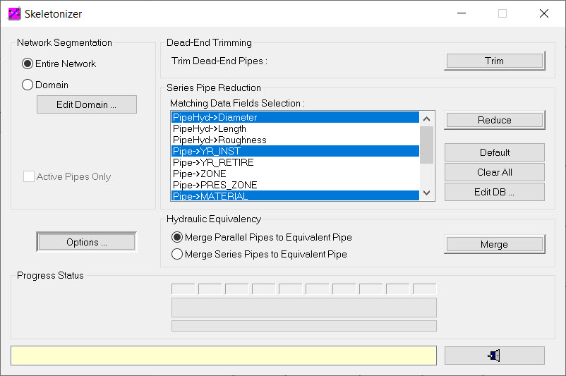
Step 2: Set Skeletonization Run Options
The first step in the network segmentation process is to define your desired network skeletonization run options. You will specify the options shown below.
- Choose the
Options button from the InfoWater Pro Skeletonizer dialog box and enter the data shown below in the InfoWater Pro – Network Skeletonizer Options dialog box.
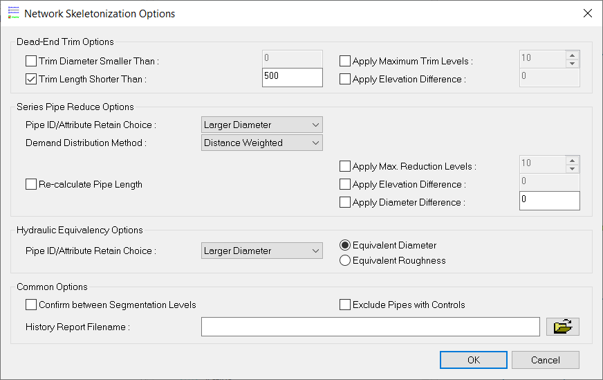
- Click on the OK button to close the dialog box.
Step 3: Launch the Network Trim Module
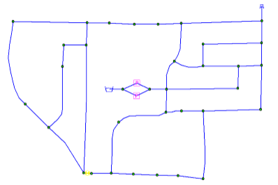
You have entered all required information to execute a network trim application. Choose the Trim button to remove all dead-end mains of length shorter than 500 ft. For this application, all dead-end mains (branching pipes) meet the minimum length criterion specified and a total of 11 pipe segments are removed from the network. These include: pipes 24, 32, 38, 42, 46, 62, 66, 72, 80, 84, and 88. The new network configuration is shown below. As shown in the figure below, the network now consists of 47 pipes and 34 junction nodes. Select the DB Editor command from the Edit menu, open the Junction Demand (Modeling) Data table, highlight the Demand1 field, and then click on the Field Statistics icon to verify that the total system demand remains 707 gpm.
Step 4: Run the Network Reduce Application
You will now run the network reduce application to merge all pipes in series that have similar diameter, material, and installation date. To accomplish this task, select “PipeHyd- >Diameter”, “Pipe- >YR_INST”, and “Pipe- >MATERIAL” data fields from the Matching Data Field Selection list in the Skeletonizer dialog box, and choose the Reduce button to execute the network reduce application.
The new network configuration is shown. The new network has been further reduced to a total of 33 pipes and 20 junction nodes. The total system demand remains at 707 gpm.
Step 5: Run the Network Skeletonizer Application
You will now launch a network Skeletonizer application and remove all 6 inch and smaller pipes. The InfoWater Pro functions will be used to perform this task.
- Close the InfoWater Pro Skeletonizer dialog box by clicking on the Close button and choose the DB Query command from the Edit menu.
- The DB Query dialog box appears on the screen. Now build a new database query that includes all pipes with a diameter less or equal to 6 inches:
-
- Choose the New
 button in the upper left-hand corner of the DB Query dialog box. Enter a query ID and description of “QRY1, Pipes 6 inches and below”.
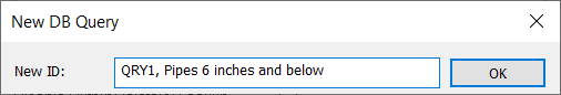
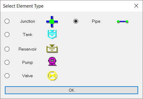
- Choose OK and the Element Type dialog box will appear.
- Choose Element Type of Pipe and click OK.
- Select the
Build Query button.

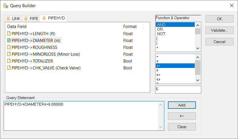
- Choose the PIPEHYD tab, select the PIPEHYD- >Diameter data field, select the “ <=” operator, type “6” in the field below the Function & Operator area. Click on the
Add button to view your query statement: PIPEHYD→DIAMETER <=6.0.
Click
OK to close the Query Builder dialog box.
- Choose the New
- Choose the Save button at the top of the DB Query dialog box and then choose the OK button to return to InfoWater Pro.
- Click on the
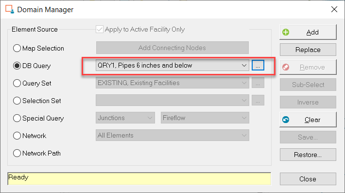
Edit Domain button from the InfoWater Pro Skeletonizer dialog box. Select
DB Query radio button in the Domain Manager dialog box, and click on the
Ellipsis
 button to open the DB Query dialog box. Select DB Query “QRY1” as the current query on the DB Query dialog box.
-
- Choose the Add button on the Domain Manager dialog box. By investigating the map display you should see all 6 inches and smaller diameter pipes highlighted in red. These include pipes 16 (River Drive) and 100 (Lake Drive).
- Choose the Reset button to restore the map color and then close the Domain Manager dialog box.
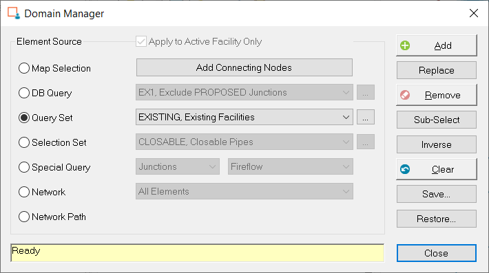
- Choose the
Edit Domain command from the
Skeletonizer dialog box menu. Select Query Set "Existing Facilities" as the current query on the Domain Manager dialog box.
-
Choose the Remove button and then close the Domain Manager dialog box. Pipes 16 and 100 have been removed from the active network. The new network configuration is shown below. The final network comprises 31 pipes and 20 junction nodes with a total system demand of 707 gpm.
Congratulations! You have now completed the Quick-Start tutorial for Skeletonizer software application.