There are five main reports available in the Report Manager to explore the results from fireflow simulations:
- Standard
- Design
- Extended Time
- Conditions
- Asset Impact
- Standard Fireflow
- Design Fireflow
- Asset Impact Reporting
Fireflow Standard Report
The first report covers the basic fireflow simulation, in which the required fireflow demand is assigned to each hydrant independently to test for adequate capacity. The available flow, which corresponds to the maximum possible while maintaining a minimum residual pressure at the hydrant, is also determined. The standard report includes static demand, static pressure, static head, fireflow demand, residual pressure, hydrant available flow, and hydrant pressure at available flow. Two additional columns appear when the velocity is also constrained, either at pipes in the model or virtual laterals feeding the hydrant.
The fireflow report contains the same information, regardless of if Design Fireflow is checked or not.

ID - Hydrant (Junction node) Identifier.
Static Demand - The regular nodal demand at the fireflow simulation time step. This value excludes fireflow demands.
Static Pressure - The nodal calculated pressure corresponding to he static demand at the fireflow simulation time step.
Static Head - Node hydraulic grade at the fire flow time step.
Fire Flow Demand - The required or user-specified fireflow demand at the current node when the hydrant is open.
Residual Pressure - The residual pressure at the current node when both the static and the fireflow demands are present. This pressure value assumes that only the current hydrant (node) is subjected to the assigned fire demand and that no other fire demands are considered simultaneously.
Hydrant Available Flow - The maximum flow that is available while maintaining the user-specified minimum residual pressure at the current node, assuming that only this hydrant (node) has fireflow demands.
Hydrant Pressure at Available Flow - Residual pressure calculated for the available flow at the current hydrant (node). This value should equal the residual pressure specified by the user.
Note: The two additional columns: Critical Pipe ID at Available Flow (optional) and Critical Pipe Velocity at Available Flow (optional) appear when the velocity at pipes and/or virtual laterals are also constrained.
Critical Pipe ID at Available Flow (optional)- The pipe within the chosen selection with the highest velocity. "* Lateral *" if the virtual lateral pipe is the one with the highest velocity. Empty if no pipes are eligible to constraint the available flow at this hydrant.
Critical Pipe Velocity at Available Flow (optional) - The velocity of the critical Pipe. Empty if no pipes are eligible to constraint the available flow at this hydrant.
Fireflow Design Report
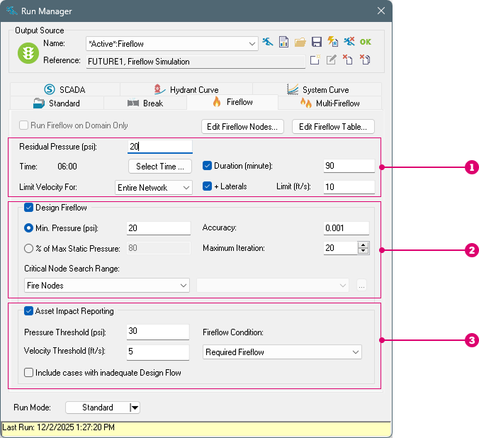
In a design fireflow analysis, additional constraints are set on the capacity of each hydrant: 1) maintain a residual pressure at the hydrant itself; 2) maintain a minimum pressure at other nodes in the network; and 3) (optionally) avoid high velocities at pipes (in the model and/or virtual laterals). The design report is only available when a design analysis is selected.
The velocity constraint is only considered in the available flow and design flow calculation if the maximum velocity option is selected.

ID - Hydrant (Junction node) identifier.
Capacity Assessment - Provides "PASS" or "FAIL" based on a comparison of the Hydrant Design Flow and the Total Demand. Capacity failure is assigned when the Hydrant Design Flow less than the requested Total Demand.
Total Demand - The total nodal demand at the fireflow simulation timestep. This value corresponds to the sum of the baseline demand (Static Demand) and the fireflow demand (Fireflow Demand) for the selected time step.
Hydrant Available Flow - The maximum flow that is available while maintaining the user-specified minimum residual pressure at the current node, assuming that only this hydrant (node) has a fireflow demand.
Critical Node ID for Design Run - The node within the Critical Node Searching Range with the lowest pressure when the current nodal junction is loaded with the total demand.
Critical Node Pressure at Available Flow - The calculated pressure at the critical node when the full available hydrant flow is applied to the hydrant node.
Critical Node Pressure at Fire Demand - The calculated pressure at the critical node when Total Demand is applied at the hydrant. Recall Total Demand = Static Demand + Fireflow Demand.
Critical Pressure for Design Run - The required minimum design pressure at all search nodes which is input by the user. This value can be customized for each junction using the Fireflow Demand table in the DB Editor.
Hydrant Design Flow - The maximum flow available at the current hydrant (node) such that the pressure anywhere within the critical node searching range (Fire Nodes, Entire Network, or Domain) does not drop below the minimum design pressure specified. Based on the critical nodes identified (junction node with minimum pressure in the critical node searching range), InfoWater Pro determines the design flow as the minimum of the adjusted flows for each junction node needed to maintain the minimum design pressure in the entire critical node searching range. Optionally, the design flow can also be constrained to avoid surpassing velocities at specified pipes. Ultimately, the Design Flow is the least flow value of all considered residual pressures and velocity constraints. This is the value that an engineer would provide to a local fire department by saying this is the maximum (theoretical) flow possible at the subject junction that still maintains adequate service.
Hydrant Pressure at Design Flow - Residual pressure calculated for the Design Flow at the current hydrant (node).
Critical Node Pressure at Design Flow - The actual pressure at the critical node at the design flow. This may differ from the Critical Pressure for Design Run (the target minimum pressure specified) when velocity constraints are enabled. With these constraints, the design flow may be limited so as not to exceed the maximum velocity, meaning that the critical node pressure will be higher than the specified minimum. There may also be small differences between the actual pressure and the target minimum pressure simply due to the search algorithm finding values that are close enough to the target in less time. Note that the legacy algorithm, which can be enabled in the Advanced Simulation Options, usually produces larger differences than the default algorithm.
Note: The two additional columns Critical Pipe ID for Design Run (optional) and Critical Pipe Velocity at Design Flow (optional) appear when the velocity at pipes and/or virtual laterals are also constrained.
Critical Pipe ID for Design Run (optional) - The pipe within the chosen selection with the highest velocity when the current hydrant is loaded with the Design Flow. "* Lateral *" if the virtual lateral pipe is the one with the highest velocity. Empty if no pipes are eligible to constraint the design flow at this hydrant.
Critical Pipe Velocity at Design Flow (optional) - The velocity of the critical Pipe when the current hydrant is loaded with the Design Flow. Empty if no pipes are eligible to constraint the available flow at this hydrant.
Fireflow Extended Time Report
In an extended time fireflow analysis, the required fireflow demand is applied at each hydrant during several time steps, starting from the selected time step and for the duration specified. The extended time report includes the results for the critical elements throughout the duration of the fireflow event. The critical element is the junction within the search scope with the lowest pressure at any point of the event and, optionally, the pipe with the highest velocity. The extended time report is only available when a non-zero duration is selected for the fireflow event.
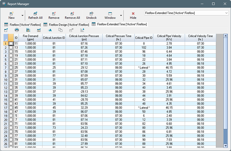
ID - Hydrant (Junction node) identifier.
Fire Demand - The required or user-specified fireflow demand at the current node when the hydrant is open.
Critical Junction ID - The node within the Critical Node Searching Range with the lowest pressure throughout the fireflow event.
Critical Pipe ID (optional) - The pipe within the chosen selection that, during the fireflow event, experienced the highest velocity. "* Lateral *" if the virtual lateral pipe is the one with the highest velocity. Empty if no pipes are selected.
Critical Pipe Velocity at Design Flow (optional) - The maximum velocity of the critical Pipe during the fireflow event. Empty if no pipes are selected.
Critical Velocity Time (optional) - The clock time at which the critical pipe experienced the highest calculated velocity during the fireflow event.
Fireflow Conditions Report - New!
The Conditions report separates the calculated hydraulic responses for the four different loading conditions at each hydrant. The conditions are Static (regular non-fireflow demand), Required (user-selected fireflow demand), Available (maximum fireflow while maintaining hydrant pressure), and Design (maximum fireflow while maintaining network service levels). Each of these conditions have a separate tab in the report, allowing to clearly understand the impact on the network of each demand level independently. The Design tab is unavailable if the design analysis was not run.
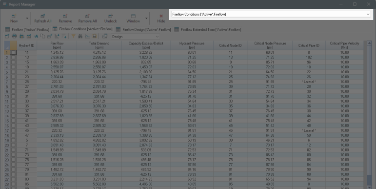
ID - Hydrant (Junction node) identifier.
Fire Flow - The fireflow demand at the current node when the hydrant is open at the simulation time step. Excludes the static/baseline demand.
Total Demand - The total nodal demand at the fireflow simulation time step. This value includes the static/baseline demand for the Static and Required conditions. It is the same as the Fire Flow for the Available and Design conditions.
Capacity Excess/Deficit - Only applies to the Available and Design conditions. The difference between the computed and the required (user-specified) fireflow demand. Positive values indicate that excess capacity is available. Negative values indicate that deficient capacity is available.
Hydrant Pressure - Residual pressure calculated for the Total Demand at the current hydrant (node).
Critical Node ID - Only applies to the Available and Design conditions. The node within the Critical Node Searching Range with the lowest pressure when the current hydrant is loaded with the Total Demand.
Critical Pipe ID (optional) - The pipe within the chosen selection with the highest velocity when the current hydrant is loaded with the Total Demand. "* Lateral *" if the virtual lateral pipe is the one with the highest velocity. Empty if no pipes are eligible to constraint the flow at this hydrant.
Critical Pipe Velocity (optional) - The velocity of the critical Pipe when the current hydrant is loaded with the Total Demand. Empty if no pipes are eligible to constraint the flow at this hydrant.
Asset Impact Reports
In addition to the above reports that focus on each hydrant included in analysis, InfoWater Pro offers reports that summarize the impact of each asset in the system, as experienced across all simulated hydrant fire flow conditions.
These reports are only available when Asset Impact Reporting is turned on.
Fireflow Pipe Impact Report
This report is used to identify capacity bottlenecks in the system, namely when certain pipes consistently experience high velocities and headloss. When fire flow requirements are a driver for pipe size, this report can help prioritize which pipes to consider upsizing.

ID - Pipe ID.
Maximum Velocity - The maximum velocity experienced by the pipe for all fireflow cases.
Maximum Flow - The maximum flow experienced by the pipe for all fireflow cases.
Maximum Unit Headloss - The maximum unit headloss experienced by the pipe for all fireflow cases.
Maximum Velocity Increase - The increase in velocity between the critical hydrant flow condition and the base flow conditions when no fire flows are occurring.
Critical Hydrant ID - The Hydrant that causes the maximum velocity in the pipe when flowing at the selected fireflow condition.
Velocity Warning Count - The total count of simulated hydrant test cases where the pipe velocity exceeded the warning threshold provided in the Run Manager.
Velocity Violation Sum - The sum of all velocity violations across all fireflow test cases where the velocity threshold was exceeded. Namely, this is the Sum of the differences between the pipe velocity and the warning threshold, considering only positive cases.
Flow Violation Sum - The sum of all flowrate violations across all fireflow test cases. A flow violation is approximated based on the velocity threshold and the diameter of the pipe. The value reports the sum of differences between the pipe flow and the flow threshold for all warning cases.
Fireflow Junction Impact Report
This report is used to identify critical pressure nodes throughout the system. The results include both the lowest pressure experienced, as well as information about the frequency of pressure warnings across all hydrant fire flow cases.

ID - Junction ID.
Minimum Pressure - The minimum pressure experienced by the junction for all fireflow cases.
Maximum Pressure Drop - The decrease in pressure between the critical hydrant flow condition and the base flow conditions when no fire flows are occurring.
Demand At Minimum Pressure - The base demand at the junction.
Critical Hydrant ID - The Hydrant that causes the minimum pressure in the junction.
Pressure Warning Count - The total count of simulated hydrant test cases where the junction pressure fell below the warning threshold provided in the Run Manager.
Pressure Violation Sum - The sum of all pressure violations across all fireflow test cases. Namely, this is the Sum of the differences between the junction pressure and the warning threshold, considering only warning cases where the pressure fell below the threshold.