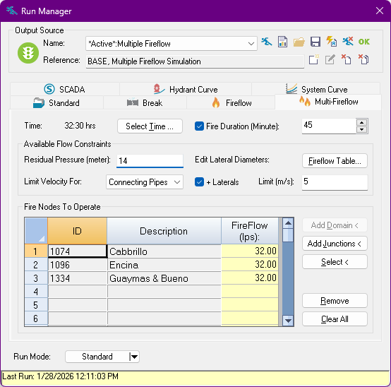
From the Run Manager Dialog Box, select the Multi-Fireflow tab to evaluate the performance and impact of multiple fire hydrants operating simultaneously. An extended time simulation applies required fire demands at each hydrant during the selected fire event time period. The hydraulic behavior of the system, as well as the residual pressure available at the hydrants, is evaluated throughout the duration of the simulation. Additionally, the instant maximum hydrant capacity (“available” flow) is evaluated at each step throughout the duration of the event, providing an estimate of how much flow can be extracted from each hydrant without the pressure dropping below a determined level. Velocities at pipes and at virtual hydrant laterals can also be used to limit the available fire flow.
Time
The time at which the fire event starts, where the required fireflow demand is added at the fire junctions. Click on the Select Time button to change this value.
Fire Duration
The duration in minutes of the fire event. The required fireflow demands are applied in all hydraulic time steps within the window defined by the event start time and this duration. If the duration option is un-checked, the fireflow demands are only applied at the single time step of the fire event start.
The whole simulation still uses the start time and duration defined in the Simulation Time options. Regular hydraulic results are available for that duration. However, fireflow demands are only applied to this window of time.
Available Flow Constraints
While the simulation applies the required fire flow demands at the fire nodes or hydrants, an instant calculation of the maximum flow available is also performed for each time step during the fire event duration. This “available” flow is limited by the pressure and velocity constraints established with these options. Whether if only the pressure values at the fire nodes are constrained, or velocity limits are also included, the constraints that are violated in the static loading case (without fireflow demands assigned) are ignored.
Residual Pressure
The available flow at each fire node is estimated such that this pressure value is maintained in all of them. If the velocity is not limited at pipes or at virtual laterals, these pressure values are the only constraints limiting the available flow values.
Fireflow Table
This button opens the Fireflow Table, which contains information used mostly for regular fireflow analyses. Only the Lateral Diameter column in that table affects multiple fireflow runs.
If the + Laterals checkbox is enabled, the available fireflow results will be limited by the velocity at virtual lateral pipes corresponding to the fire nodes selected for the analysis. The virtual lateral pipes connect the fire node to the actual hydrant. Their velocity is computed by taking into account the values in the lateral diameter column. Empty diameter values or values of zero are interpreted as there not being a lateral pipe at all.
Velocity Limit
Use the drop-down menu next to Limit Velocity For: to select which pipes should have their flow velocity limited. The options are:
- No Pipes: Velocities are not limited at model pipes.
- Connecting Pipes: Limit the velocity at those pipes directly connected to the fire nodes.
- Entire Network: Limit the velocity at all the pipes in the model.
- Domain Pipes: Limit the velocity at the pipes in the domain (if any).
Check the + Laterals checkbox to limit the velocity at any defined virtual hydrant lateral pipes at the selected fire nodes. Virtual laterals, which are pipes not explicitly defined as part of the model, connect the fire nodes with the actual hydrants. These virtual laterals are configured in the Fireflow Table, where its diameter is entered. The maximum velocity allowed for the available flow case is defined in the text edit next to Limit:. This limit applies both to actual and virtual lateral pipes.
Fire Nodes To Operate
This table lists which nodes in the model have hydrants to be operated as part of the analysis. Each row includes the identifier (ID) of the node, its Description, and the required FireFlow demand to be applied in addition to any regular demands during the fire event.
Add Domain
Adds all the junctions in the Domain to the table.
Add Junctions
Allows manually appending additional junctions to the table directly from the Map. Once on the map, select the junctions to append, then right-click with the mouse, and select Enter to commit and append the selected junctions (or Cancel to return).
Select
Allows manually replacing the currently highlighted junction in the table from the Map. Once on the map, select the junction to serve as replacement. Right-click with the mouse and select Cancel to return without replacing.
Remove
This button removes all highlighted junctions from the table.
Clear All
This button removes all junction from the table. Confirmation is required to proceed.