This feature lets utilities identify high-risk pipes proactively, supporting data-driven maintenance and investment decisions. It clusters pipes into isolation areas to improve efficiency by reducing computational overhead and avoiding redundant calculations. It also offers more flexibility and user input options than previous solutions.
Criticality Analysis is a feature designed for water utilities to assess the risk condition of underground pipes and identify critical assets for repair or replacement. It leverages advanced spatial data modeling and cloud-based parallelization to overcome the limitations of legacy tools, providing a scalable, flexible, and accurate approach to network risk assessment.
Data Tab
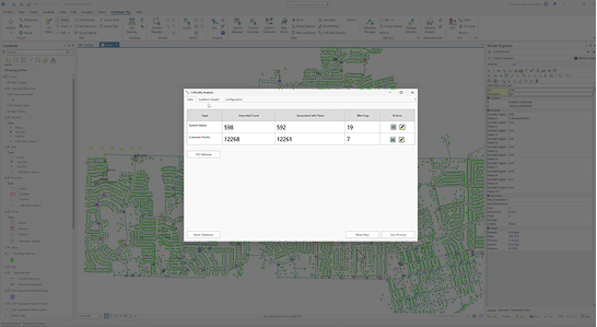
The Data Tab is used for importing and reviewing the required input data used in Criticality Analysis. Data is imported through the GIS Gateway and processed through the Geo-Process tool. The table shows the status of input data during processing.
Definitions:
- GIS Gateway – Opens the GIS Gateway for importing system valves and/or customer points. These object types can be found near the bottom of the Network Data Source Type list.
- Reset Database – This action erases all Criticality Analysis results and input data. It offers a way to start over in the analysis if necessary.
- Reset Map – This clears the map of any Criticality Analysis map layers.
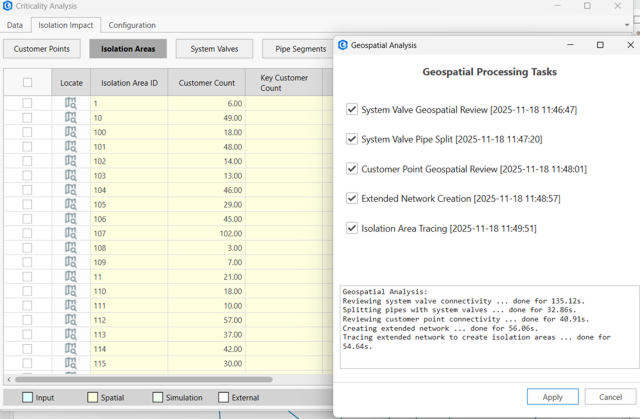
- Geo-Process – This action processes the valve and customer data (if available) through several steps to associate them with the network and trace out isolation areas. While the Geospatial processing tasks can be selected and run on-demand, all tasks must be run sequentially in order to have complete results.
- System Valve Geospatial Review - This step joins system valves to the nearest hydraulic model layers and generates warnings when a suitable connection cannot be made to the network.
- System Valve Pipe Split - This step generates a pipe segment layer with splits at locations where system valves are on top of pipes.
- Customer Point Geospatial Review - This step joins customer points to the pipe segment layer and generates warnings if outside of the tolerated range.
- Extended Network Creation - This step gathers hydraulic and information data from the network in preparation for generating isolation areas.
- Isolation Area Tracing - This step generates isolation areas based on tracing the network to system valve points.
Isolation Impact Tab
The Isolation Impact tab provides interactive tables of results and related data for evaluating the criticality impact of isolating each asset in the system.
The tables support sorting and zooming to objects on the map.
Use the Map Theme tools configured in the Configuration tab to apply results on the map.
Hydraulic simulations for assessing isolation impact are available from the Isolation Areas table. Select desired areas and click Run to process hydraulic analysis. This triggers a simulation for each area to be isolated, following the Configuration Settings.
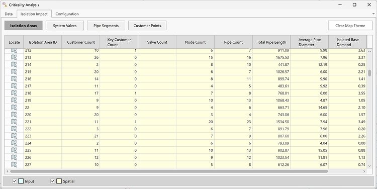
Isolation Areas
Spatial Fields:
- Customer Count – The total number of customer points associated with pipe segments inside the isolation area. These customers will lose water supply in the event of an isolation.
- Key Customer Count – The count of customer points designated as key customers. This can be used to separate critical customers like hospitals, schools, and nursing homes for example.
- Valve Count - The count of valves required to isolate the area. In the current version, this is limited to valves located on pipes.
- Node Count - The count of nodes within the isolation area. This does not include nodes co-located with system valves at the boundary of the area.
- Pipe Count - The count of pipe segments within the isolation area.
- Total Pipe Length - The total length of pipe segments within the isolation area.
- Average Pipe Diameter - The length-weighted average diameter of all pipe segments within the area.
- Isolated Base Demand - The total base demand, ignoring the effects of Patterns, from all Junctions within the area. This does not include nodes co-located with system valves at the boundary of the area.
- Pressure Zone - The first value found in the Zone field among pipe segments in the area. In the unlikely event that an isolation area spans multiple pressure zones, only the first value is used.
Simulation Fields
- Run Status - This field reports whether the isolation simulation was successful or if the run failed.
- Event Demand Change - The change in total satisfied demand relative to the Base simulation without isolation. The comparison is calculated during the isolation timestep. When pressure dependent demand is enabled in the Simulation Options, this accounts for partial reductions in demand due to inadequate pressure.
- Event Demand Change Percent - The change in total satisfied demand relative to the Base simulation without isolation. This is calculated as Event Demand Change divided by Base total demand.
- Additional Isolated Junctions - The total count of junctions isolated from supply that were not isolated in Base simulation. This includes downstream areas outside of the direct isolation area which no longer receive supply.
- Additional Junctions below min Pressure - The count of junctions with minimum pressure below the Low Pressure threshold which did not exceed the pressure warning in the Base simulation without isolation.
- Additional Junctions above max Pressure - The count of junctions with maximum pressure above the High Pressure threshold which did not exceed the pressure warning in the Base simulation without isolation.
- Additional Pipes above max Velocity - The count of pipes with peak velocity above the High Velocity threshold which did not exceed the velocity warning in the Base simulation without isolation.
System Valves
Input Fields:
- Life Cycle Status - Indicates if a valve is retired or in-service. Currently this doesn't impact a valve’s inclusion in the Geo-Processing.
- Normal Status - Indicates if a valve is normally closed or open.
- Closable - Indicates if a valve is closeable or not. Currently this does not impact a valve’s inclusion in the Geo-Processing.
- Install Date - The install date of the valve in text format, which can be relevant when assessing valve risk of failure.
- Diameter - The diameter of the valve, which can be relevant when assessing the risk of valve failure.
Spatial Analysis Fields:
- Distance - The distance of the valve from its associated model object.
- Association Type - Indicates whether the valve is associated with a pipe, junction, or valve.
- Association Status - This status indicates if the valve is actively used in the analysis or if there is an error preventing its use:
- Active - The valve is used tracing isolation boundaries.
- On top of a junction or valve not having 2 connecting pipes - System valves are not considered on dead ends or intersections with 3 or more pipes.
- Too far from pipes - The valve is located outside the specified distance tolerance from pipes as defined in the Configuration tab.
- Cannot split the associated pipe - This can occur when the valve is within the buffer distance from pipes, but it would intersect at an end point. Consider fixing geometry to snap the valve to the node or on a pipe.
- On a pipe connected to a pump or valve - System valves are not allowed in these cases. Consider relocating the valve or removing it.
- Isolation Area Upstream - Isolation area ID on the upstream side of the valve.
- Isolation Area Downstream - Isolation area ID on the downstream side of the valve.
- Combined customer count - The sum of customers enclosed within the isolation areas upstream and downstream of the valve.
- Combined key customer count - The sum of key customers enclosed within the isolation areas upstream and downstream of the valve.
- Combined pipe count - The count of pipe segments enclosed within the isolation areas upstream and downstream of the valve.
- Combined node count - The count of nodes enclosed within the isolation areas upstream and downstream of the valve.
- Combined isolated base demand - The sum of junction base demand enclosed within the isolation areas upstream and downstream of the valve. This neglects any factors from the associated demand patterns.
Pipe Segments
Input Fields:
- Is Key Customer - This flag is used to designate critical customers where isolation can have detrimental impacts. These customers are reported separately in criticality results.
- Billing Value - this optional field can be used to track the billed volume of water delivered to each customer which can be used when considering the criticality of impact.
- Billing Date - this optional field stores the date of reading for the billing value.
Spatial Analysis Fields:
- Model Pipe ID - The nearest model pipe segment ID each customer is joined to.
- Distance to Pipe - The distance between the customer point and the associated pipe segment.
- Association Status - This indicates whether the customer is associated to a pipe and active in the analysis, or if it’s too far from pipes as defined by the tolerance in the Configuration tab.
Configuration Tab
Geo-Processing
- Valve to pipe distance tolerance - System valves must be within this distance to be associated with pipes.
- Customer to pipe distance tolerance - Customer points must be within this distance to be associated with pipes.
- Max pipe size for customer connection - This can be used as a diameter threshold to distinguish transmission mains which do not receive customer connections.
Map Theme Settings
This tab is used to configure basic Map Themes for Criticality Analysis. Once the layers have been added to the map, ArcGIS Pro Symbology and labeling tools can be used for fine-tuning advanced maps.
- Field - Choose and available field for the selected layer to base the Map Theme on.
- Set Break - Select to populate the table of map display rows based on the data and number of classes.
- Show Label - When enabled, the map theme will also add basic labels to the map.
- Apply Theme - This applies the current settings as a map theme on the map.
- Save Configuration - Saves the current settings. These settings are used when clicking Generate Map Theme from the Isolation Impact tab.