Linear Feature Extraction
Linear Feature Extraction allows users to create linear elements from InfraWorks surface and extract those linear elements.
In this month’s Have You Tried article, we’ll take a closer look at the Linear Feature Extraction feature in InfraWorks. Linear Feature Extraction isn’t new, but if you have never used it, you might want to find out how it can help expedite your workflow.
Each month, we profile a useful feature or workflow in InfraWorks. We look across what's new, what's been around for a while, and identify features that could improve your experience with InfraWorks while making you and your team more productive.
What is it?
Linear Feature Extraction allows users to create linear elements from InfraWorks surface and extract those linear elements. The InfraWorks surface can be imported or generated from ReCap data (point clouds). For surfaces generated using ReCap, you can automatically identify linear features to extract.
Why use it?
Linear feature extraction allows you to manually or automatically extract a line from your InfraWorks model. This line could be pulled from:
- Breaklines where there's a change in the slope of terrain such as the crown of the road, top and bottom of a curb, bottom of a drainage system.
- Line demarcation to signify the presence of a linear entity such as the lines of roads, top of rails, and boundaries.
- 3D linear features such as powerlines.
Extracting the linear features as individual elements using this workflow can be very valuable to perform conceptual and detailed design.
Where is it?
To use Linear Feature Extraction, click Manage glyph Point Cloud Linear feature Extraction Linear Feature Extraction (Linear Feature Extraction).

How do I use it?
With linear feature extraction, you can model linear features of roads from extractions from point cloud data created in ReCap. After extracting point cloud data, you can create new linear features using automatic or manual workflows.
After selecting the Feature Line Extraction tool in the toolbar, toggle Automatic on to use the Automatic method for extraction, or toggle it off to use the Manual method.
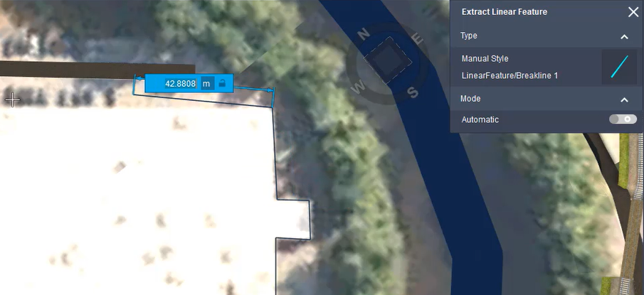
Automatic Method
Using the automatic method, after defining two points on the desired road, InfraWorks will automatically generate a linear feature using the point cloud data.
After selecting the Extract Linear Feature tool, select the correct line style for the feature you want to extract.
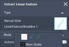
For more line styles, click "More Styles" to see all available linear feature styles.
When using the Automatic method, you must pick the correct style at this point for the linear feature to be successfully extracted.
Next, click two points on the target linear feature. Click to specify the starting point, and double-click close to the starting point to set the draw direction and generate the linear feature.
Manual Method
Using the manual method, position points along the desired road in the point cloud to create a linear feature. The manual method is best used for more accurate linear extraction of complex areas.
Next, select the correct line style for the feature you want to extract.
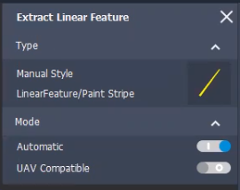
For more line styles, click "More Styles" to see all available linear feature styles.
Click to select points along the line, and double-click to complete the feature.
Click and drag the points in canvas as needed to modify their position.
You can access additional editing options on the right-click context menu.
Exporting a Linear Feature
Export features extracted from point cloud data for downstream design and analysis.
After you extract a terrain and vertical or linear features from point cloud data, you can export these features for use in other products, such as Civil 3D. Vertical and linear features are extracted to a shapefile (SHP) or CSV formats, and vertices data for transverse lines are extracted to a CSV file.
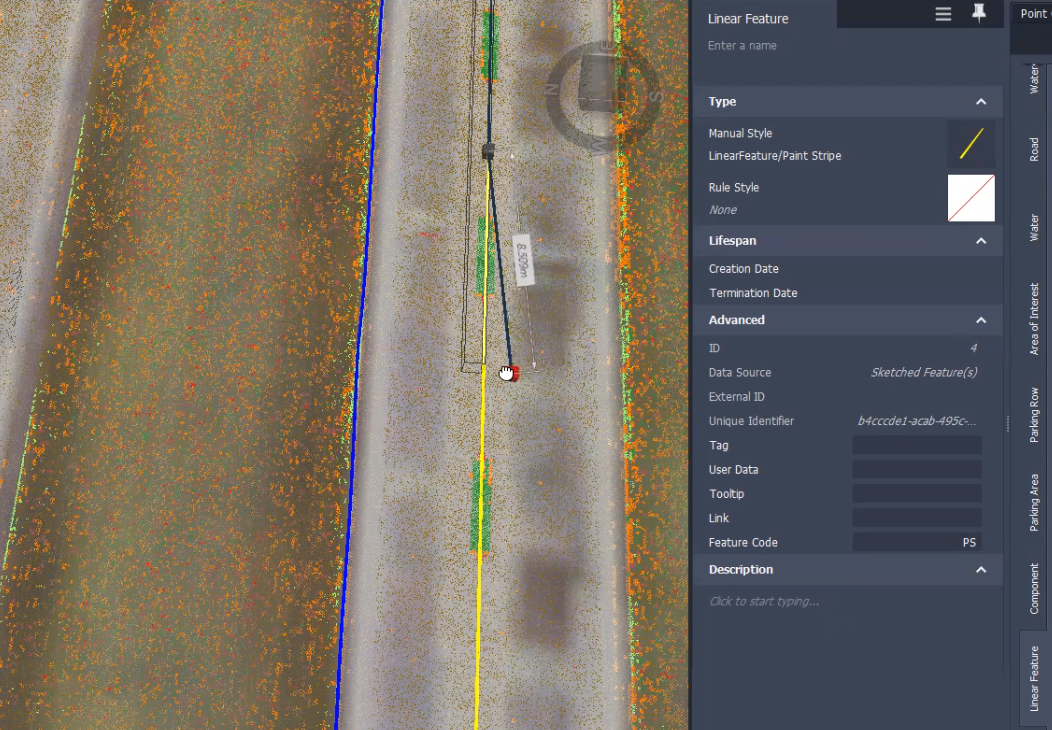
It's important to note that each Linear Feature line style is assigned a Feature Code. When exporting linear features, this code is used to set the line style in the target application, such as Autodesk Civil 3D.
To modify the Feature Code, double-click the line style on the Linear Feature tab of the Style Palette.
Click Manage
 Point Clouds
  Export Point Cloud Extraction.
In the Export Point Cloud Extraction dialog, specify the options for extraction:
Ground Grid Points Only: Select to export the extracted terrain (only ground points are exported)
| --- | --- | | Linear | Extracted linear features, such as lane lines, curb lines, and centerlines. | | Transverse Vertices | Vertices for generated transverse lines created for extracted linear features. | | Vertical | Extracted vertical features, such as trees, street lights, and signs. | | Target CS | Select the coordinate system compatible with the target application for the exported data. | | Save Folder | Specify the folder location to save the data files. |
Note: Only the features extracted from point cloud data are converted during export to use the target coordinate system. The exported ground (RCS file) will be exported in the original RCS coordinate system.Click Start Export. The data is saved in the format and to the folder location specified.