To create adaptive trees
Create adaptive or Level of Detail (LOD) trees to bring life to your models without impacting performance.
To increase performance of an object, use Level of Detail (LOD). At further camera distances, the model is replaced with another version, using a lower polygon count.
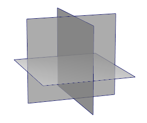
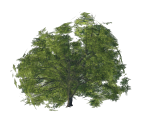
To start building a low-polygon count tree in a 3D modeling application, use a plane consisting of two polygons and have an image of the tree you wish to create for texture.
To ensure that the tree is visible from all sides, take a second plane and rotate it 90 degrees for a side view, and a third plane for the top view.
To texture all of the planes with a single image, use UV mapping to separate the planes to different positions of your texture (from the 2D tree image). Laying out the UVs is the first step in the process of making a 2D image representation of a 3D object's surface.
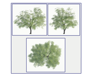
Create a larger square plane, representing the size of the image.
For every plane of the low-polygon tree, make a copy of your original tree, group it with the dependent plane, and place the groups inside the larger plane.
Rotate the groups to reflect the orientation of the planes, so that every plane is lying flat on the large plane.
Select all of the planes, including the large plane, and assign a planar UV projection to create matching UV coordinates.
Create an orthographic camera and place it in front of the large plane. Scale the view size to match the large plane.
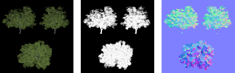
Hide all planes and render an image of your original tree with "separate alpha" selected, to use it for texturing.
You can also render a normal pass. Do not use shadows for the rendering to avoid different light directions in InfraWorks.
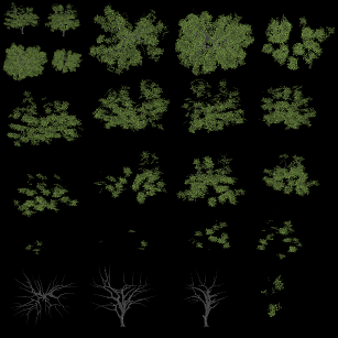
The following image shows, from left to right, color-texture, alpha-texture, and normal-texture.
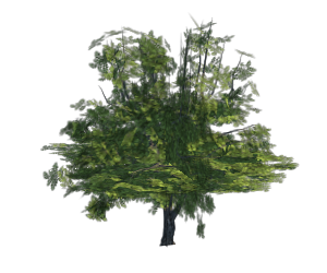
Unhide the planes, and assign a material.
Use the rendered textures for the color and transparency channel of your material. If you have a normal texture, use it for normal mapping.
Bring your groups back to their original position.
Each of the planes has a front and back side, depending on their normal orientation. In InfraWorks there is an option to turn off visibility for backfaces.
To make sure the planes will be visible from both sides, make copies of them and flip their normal orientation.
You can control face orientation by using backface-culling or displaying normals.
Collapse the planes to a single object and export the object to FBX, OBJ, or DAE format.
Note: FBX format is recommended because normal information is supported properly by this format.
To create section parts
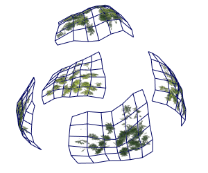
To create another LOD version with more depth in perspective, you can cut your tree into sections.
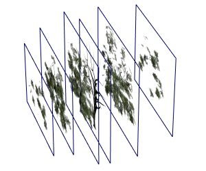
An easy way to do this is to use camera clipping for rendering. You can define a near and a far distance for the camera, so your rendered images will only include content from this range. This way you can create planes for front, back, left, right, and top of your tree with varying areas of depth.
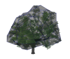
You can also model a shell of the tree and use it on the outside for a better shape.
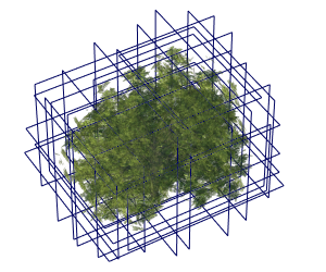
Cut the tree in parts for all sides so you can use UV mapping and texturing like you did for the planes.
Visit the Have You Tried: Vegetation? article to learn how you can use vegetation to provide a more complete vision of an InfraWorks project.