Bored Ring Tunnel Parameter Reference
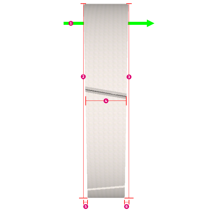
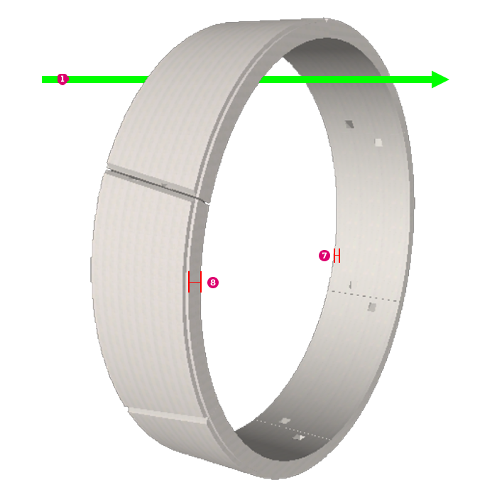
Bored Ring tunnel regions consist of a series of rings placed sequentially. Their parameters define diameter, length, rotational position, and taper.
| Parameter Description | Content Parameter | Parametric Value | InfraWorks Set/Read | Inventor | Revit |
|---|---|---|---|---|---|
| Start Diameter | Diameter1 | The diameter of the ring at the start position (x=0, z=0) of the segment. | Yes/No | No | No |
| End Diameter | Diameter2 | The diameter of the ring at the end position of the segment. | Yes/No | No | No |
| Start Wall Thickness | WallThickness1 | The segment thickness at the start face of the ring. | Yes/No | No | No |
| End Wall Thickness | WallThickness2 | The segment thickness at the end face of the ring. | Yes/No | No | No |
| Start Taper | Taper1 | The perpendicular offset from the top of the ring to the bottom at the start face of the segment. | Yes/No | No | No |
| End Taper | Taper2 | The perpendicular offset from the top of the ring to the bottom at the end face of the segment. | Yes/No | No | No |
| Segment Length | SegmentLength | The length of the segment as measured from the center of the start face (x=0, y= 0, z= 0) to center of the end face. | Yes/No | No | No |
| Number of Segments | NumberOfSegments | The number of segments along the tunnel region. | Yes/No | No | No |
| Number of Positions | NumberOfPositions | The number of angle positions that a ring can rotate to maintain alignment with the road alignment. The increment for these angles is 360/NumberOfPositions degrees. If the Start Taper is positive, the rotation is counterclockwise when looking at the part origin from the positive end of the Z axis. If the End Taper is positive, the rotation is clockwise. |
Yes/No | No | No |
 |
 |
 Direction of Alignment Direction of Alignment |
 Taper1 Taper1 |
 TunnelDiameter1 TunnelDiameter1 |
 Taper2 Taper2 |
 TunnelDiameter2 TunnelDiameter2 |
 WallThickness1 WallThickness1 |
 SegmentLength SegmentLength |
 WallThickness2 WallThickness2 |
Bored Ring Segment Placement
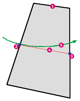
Bored Ring tunnel regions consist of a series of sequentially placed rings. The SegmentLength parameter determines the spacing of these ring segments which are placed with their centers aligned as closely as possible with the road alignment.
The first ring is positioned at the tunnel region start, and aligns with the tangent of the alignment at the region start.

 Ring Segment Ring Segment |
 Tangent Tangent |
 Ring Back Center Ring Back Center |
 Alignment Alignment |
 Ring Front Center Ring Front Center |
Subsequent rings are placed so the start (back) face of each ring is flush with the end (front) face of the preceding ring.
Ring Segment Rotation
Each ring is then rotated so its front center is as close as possible to the alignment without introducing swerving (see below). The ring segment parameters defines a number of equidistant positions (NumberOfPositions), and each position in the ring must line up with a position in the preceding ring.
For example, if the number of positions is 6, then the allowed angles of rotation are 0, 60, 120, 180, 240, and 300 degrees.
The rotation is around the y-axis of the coordinate system of the ring segment. Due to the tapering (face skews) of the part, each rotation angle puts the front centre at a different position with respect to the alignment.
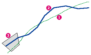
The angle of rotation for the next segment aligns the ring most closely with the alignment without introducing swerving. Swerving happens if the segments stray from the alignment due to a very tight curve and the ends of subsequent rings converge too quickly to the alignment and end up crossing to its other side.

 Alignment Alignment |
|
 Ring Tangents (back to front) Ring Tangents (back to front) |
|
 Ring Segment Ring Segment |
This is remedied by checking each possible position of each ring to determine the minimum turning radius of the subsequent rings. If this minimum turning circle intersects the alignment then swerving can happen. The position chosen for the ring is the one where the end of the ring is closest to the alignment without introducing swerving. If all positions cause swerving then the closest position is chosen.