Civil Structure Geometry Clipping Planes
Use clipping planes to temporarily expose the interior of your civil structure to help design and document your model.
To enable and view clipping planes, select your civil structure, right-click the model, and select Show Clipping Planes. Deselect to hide clipping planes and their flags.
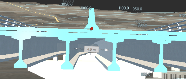
The clipping plane displays as a flag above its specified location and has two states: unclipped (maroon) and clipped (blue). Click the flag to switch states.
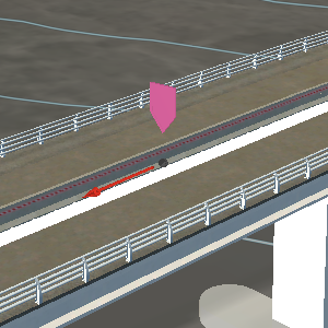
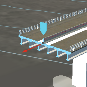
When enabled, you can manually reposition the clipping plane location. The red arrow displayed is a grip that can be moved along the structure.
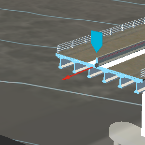
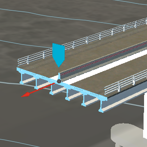
When clipping planes are enabled, the Clipping Plane toolbar displays. This toolbar allows for more finite control over the positioning of the planes.
 Reverse Direction. Swaps the clipped geometry to the opposite side of the plane. Click again to revert to the original clip.
 Align Camera. Aligns the camera to view the clip plane perpendicularly.
 Clip Terrain. Allows the corresponding terrain and surface layers to be clipped by the plane along with the civil structure geometry.
- Offset. The location of the currently selected clip plane from the Start Station of the structure.
- Skew. The degrees of horizontal rotation of the plane around its station of placement.
 Create Plane. Adds a new clipping plane along the civil structure. Move your cursor to the desired location along the structure and press Enter.
 Delete Plane. Removes the currently selected clipping plane.
Clipping planes are displayed in snapshot and storyboards.
If you save a bookmark with an active clipping plane, when you return to the bookmark, the clipping plane displays.