Pier Parameter Reference
Pier specific parameters control longitudinal placement, longitudinal slopes, vertical placement, lateral widths, and skew.
| Parameter Description | Content Parameter | Parametric Value | InfraWorks Set/Read | Inventor | Revit |
|---|---|---|---|---|---|
| Vertical offset from bottom | BottomVerticalOffset | The vertical offset at the bottom of a pier. Positive values are upward. Negative values are down. | Yes/No | No | Yes |
| Integral pier that does not require bearings | IsIntegralPierThatDoesNotRequireBearings | Specifies a pirer does not require bearings. Either True or False. The pier has no bearings and the girders sit directly on the pier top if set to True. | Yes/No | No | No |
| Match by surface to bearings | MatchBySurfaceToBearings | Defines how piers vertically aligned with their bearings and foundations. Either True or False. True aligns with the meshes of the pier. False aligns with approximate planes of the pier top. | Yes/No | No | Yes |
| Pier cap depth | PiercapDepth | The height of the pier cap measured from the bearings to the pier. | Yes/No | No | No |
| * Pier cap left width from center | PierCapLeftWidth | The distance from the center of the pier cap to its left edge. | No/Yes | No | No |
| * Pier cap right width from center | PierCapRightWidth | The distance from the center of the pier cap to its right edge. | No/Yes | No | No |
| Pier cap section width 1 | PierCapSectionWidth1 | The width of part of pier cap behind the origin. | Yes/No | No | No |
| Pier cap section width 1 | PierCapSectionWidth2 | The width of part of pier cap ahead of the origin. | Yes/No | No | No |
| Pier cap section slope 1 | PierCapSectSlope1 | The longitudinal slope of the part of the pier cap behind the origin when MatchBySurfaceByBearings is set to False. | Yes/No | No | No |
| Pier cap section slope 2 | PierCapSectSlope2 | The longitudinal slope of the part of the pier cap ahead of the origin when MatchBySurfaceByBearings is set to False. | Yes/No | No | No |
| Pier cap top left slope in percentage | PierCapTopLeftSlopeInPercentage | The lateral slope of pier cap to the left of the origin when MatchBySurfaceByBearings is set to False. | Yes/No | No | No |
| Pier cap top right slope in percentage | PierCapTopRightSlopeInPercentage | The lateral slope of pier cap to the left of the origin when MatchBySurfaceByBearings is set to False. | Yes/No | No | No |
| Pier cap top slope | PierCapTopSlope | The lateral slope of the pier cap. | No/Yes | No | No |
| * Overall height of pier | PierHeight | The distance between the pier bearings and foundation. | No/Yes | No | No |
| Skew | Skew | The horizontal skew information stored in the pier part. InfrsWorks ignores this information and skews as needed. | Yes/No | No | No |
| Pier cap step height | StepHeight | The height of the pier cap step measured from the bearings of the shallow deck and lower cap surface. | No/Yes | No | No |
| Vertical offset from top | TopVerticalOffset | The vertical offset at the top of a pier. Positive values are upward. Negative values are down. | Yes/No | No | Yes |
Pier Placement
Pier origins are defined by lateral, longitudinal, and vertical dimensions. Vertical dimensions are explained in detail in the following Vertical Placement section.
Lateral and Longitudinal Dimensions. Pier placement is intended for their origins to be under the road alignment. Piers offset along the road from the bridge start. These are not configurable beyond offset in InfraWorks so additional adjustments need to be made in Inventor or Revit to move geometry relative to the origin.
Vertical Dimension. Vertical placement is contingent on its MatchBySurfaceToBearings parameter. When False, the origin must be at the bottom of the pier, where the pier meets the terrain, or at the top of its foundation. Vertical dimensions are explained in detail in the following Vertical Placement section.
Vertical Placement
Vertical alignment for piers is initially controlled by the MatchBySurfaceToBearings parameter.
Setting this to True will vertically align the pier using its meshes. This is a more exact method, ensuring that bearings touch the pier even if it has an irregular top surface. Because pier meshes must be generated during initial creation, this is a slower method to implement. Piers will then vertically align to bearings and foundations regardless of the elevation of the origin of the pier.
Setting this to False will vertically align the pier using approximated planes of the pier top. 4 planes are considered: left back, right back, left front, and right front. This is a faster yet less precise method. The bearings and pier touch only if the pier top aligns with these 4 planes. The foundation top aligns with the origin of the pier, so the origin is expected to be at the bottom of the pier. Otherwise, the pier and foundation cannot vertically align.
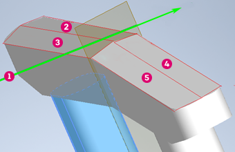
 Alignment Alignment |
 Right Front Plane Right Front Plane |
 Left Front Plane Left Front Plane |
 Right Back Plane Right Back Plane |
 Left Back Plane Left Back Plane |
The MatchBySurfaceToBearings parameter setting affects other parameters as well.
Pier Height
The PierHeight parameter represents the overall height of the pier. It is calculated to fit between the bearings and foundation. If the source part does not set the total height to this value, then the pier may be too tall or too short. The behavior in this case depends on MatchBySurfaceToBearings.
When set to True, bearings and foundations will adapt to the pier. Bearings stretch to reach the top of piers that are too short. Foundations shorten to make room for a pier that is too tall.
When set to False, no adjustments are made. If a pier is too short, then there is a gap between pier and bearings. If the pier is too tall, it will protrude into the bearings, and possibly the girders and deck.
Pier Cap Depth
The PiercapDepth represents the vertical height of the pier cap and is applicable only when MatchBySurfaceToBearings is set to False. It is set by the part and is used to estimate the minimum height of a pier. The minimum height of pier columns is assumed to be 1m, so Minimum_height = PiercapDepth + 1m.
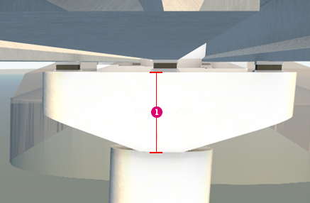
 PiercapDepth
If the distance between the bearings and the foundation is under this minimum height, the foundation is shortened so that the distance is at minimum height.
When MatchBySurfaceToBearings is set as True, the minimum height estimate is not needed. It is inferred from the meshes created for the pier. The foundation is shortened when PierHeight is less that the actual height of the pier.
Step Height
The StepHeight parameter is only used when a pier has a stepped cap. Calculations are only applicable when MatchBySurfaceToBearings is set to False. Step height calculates to reduce the stretching of bearings under the shallow girders at the pier top.
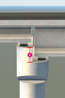
 StepHeight
Vertical Offsets
The TopVerticalOffset and BottomVerticalOffset parameters adjust the pier top and bottoms up and down and are applicable only when MatchBySurfaceToBearings is set to True.
In most cases, pier placement is accurate, but in some situations it may be necessary to make adjustments. Positive values adjust geometry upward nd negative values adjust downward. No adjustments are made to other features. So, if the pier and bearings (or foundations) touch when offsets are set to 0, then they will not touch for other values.
The following image of a pier includes bolts that are supposed to go through the foundation. By default the foundation top will be at the bottom of the bolts (BottomVerticalOffset = 0).
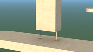
However, BottomVerticalOffset when set to negative, can adjust the bolts to go through the foundation as expected.
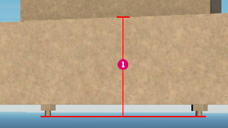
 BottomVerticalOffset = -1.2
Lateral Widths
LeftWidth and RightWidth are calculated based on the left and right widths of the deck at the pier. Deck widths are measured perpendicular to the alignment. Left deck width is the distance from the alignment to the left edge of deck. Right deck width is the distance from the alignment to the right edge of deck.
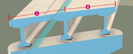
 LeftWidth LeftWidth |
 RightWidth RightWidth |
Pier left and right width are measured along the skew line of the pier. So the following calculations are made when the alignm,ent is straight:
- LeftWidth = deck_left_width * cos(skew)
- RightWidth = deck_right_width * cos(skew)
Longitudinal Widths
Piers express longitudinal widths of a pier cap with the PierCapSectionWidth1 and PierCapSectionWidth2 parameters. These dimensions determine the default longitudinal positions of the bearings when the pier has 2 rows of bearings. The back row is placed midway between the back edge of the pier cap and the end positions of the girders above the row. Similarly, the front row is midway between the start positions of the front girders and the front edge of the pier cap.
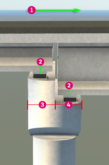
 Increasing Station Direction Increasing Station Direction |
 PierCapSectionWidth1 PierCapSectionWidth1 |
 Bearing Center Position Bearing Center Position |
 PierCapSectionWidth2 PierCapSectionWidth2 |
Pier Top Slopes
PierCapTopSlope calculates a dimension that allows the top of a skewed pier to follow the alignment grade:
- PierCapTopSlope = arctan(tan(alignment grade (as an angle)) * sin(skew).
This does not take into account deck superelevation or depths of girders or bearings.

 Alignment Grade Alignment Grade |
 PierCapTopSlope PierCapTopSlope |
The other dimensions implemented by the pier provide information on the pier top slopes. These are only used when MatchBySurfaceByBearings is set to False. They allow InfraWorks to determine more accurate top planes for the pier.
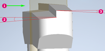
 Direction of Alignment Direction of Alignment |
 PierCapSectSlope2 PierCapSectSlope2 |
 PierCapSectSlope1 PierCapSectSlope1 |

 PierCapTopLeftSlopeInPercentage PierCapTopLeftSlopeInPercentage |
 PierCapTopRightSlopeInPercentage PierCapTopRightSlopeInPercentage |
Skew
Skew specifies a counterclockwise rotation of the pier around the Z-axis of the coordinate system of the road. This rotation is handled by InfraWorks outside of the pier. However, skew information is stored in the pier though it is ignored by InfraWorks.