To prepare a flood simulation
Define a flood simulation study area boundary, specify inflow and outflow location, input parameters, then run the simulation. Depending on how you configure inflow parameters, you can simulate inland or coastal flooding scenarios.
Attention: InfraWorks only supports flood simulation capabilities for users who have purchased and installed the third-party RiverFlow2D plugin available from Hydronia, LLC.
Click Analyze
 Drainage
  (Flood Simulation).
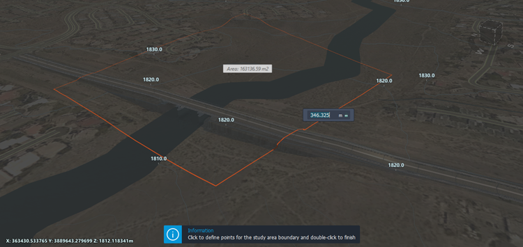
InfraWorks prompts you to define a polygonal boundary for the flood simulation study area. Left-click to place each point. Double-click to complete the polygon.
Define the inflow location(s). You can use either a single inflow, or multiple inflows. Do either:
- For a single inflow, click once to define the inflow start station, then drag your cursor along the boundary until you reach the desired end point for the inflow. Double-click to place the inflow end point.
- For multiple inflows, click once to define the initial inflow start station, and single-click to place the end point for your first inflow. You can then repeat this procedure to define additional inflows. Double click to place the last inflow end point.
Define the outflow location. Click once to the define the outflow start station, then drag your cursor along the boundary until you reach the desired end point for the outflow. Click again to place the outflow end point.
Note: Click and drag any inflow or outflow start or end station to modify its location.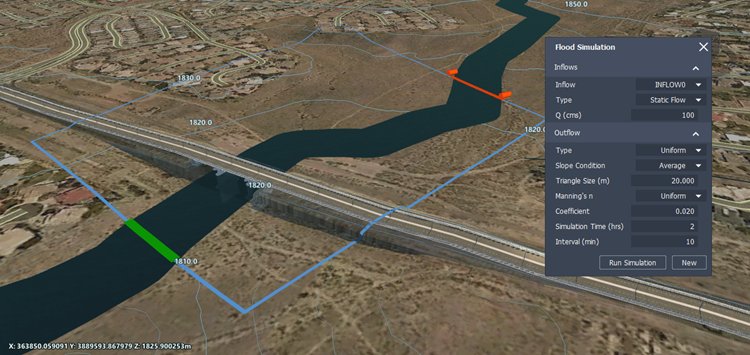
The Flood Simulation panel allows you to specify inflow and outflow types, cubic volume of inflowing water, a uniform or distributed Manning's coefficient for your simulation, simulation time and intervals, as well as triangle size.
| Inflow type | Choose between Static, Discharge vs. Time, or Elevation vs. Time inflow types. Static: The inflow is a fixed, consistent flow rate. If you choose Static, you will be prompted to define a Q value that represents the inflow volume of water in cubic meters/second. Discharge vs. Time: The inflow volume of water changes over time. The Flood Simulation panel prompts you to specify units of measurement and select a data file from your local system that defines your inflow boundary condition, also known as a hydrograph. You can create your own hydrograph inflow file for Discharge vs. Time inflow using a text-editing application. Elevation vs. Time: The inflow is based on changes in elevation over time, rather than discharge volume over time. This allows you to model the effects of a coastal storm surge or sea level rise. The Flood Simulation panel prompts you to specify units of measurement and select a data file from your local system that defines your inflow boundary condition, also known as a stage hydrograph. You can create your own stage hydrograph inflow file for Elevation vs. Time inflow using a text-editing application. |
| Q (cubic meters/second) | If you chose a Static inflow type, specify the inflow volume of water in cubic meters/second. |
| Outflow type | Choose between Uniform or Freeflow outflow. Uniform: If you choose Uniform, you will be prompted to specify a slope condition: Choose Average slope condition to use an outflow rating table that is based on the computed average slope entry condition. The value is calculated every .05 meters, starting from the lowest bed elevation in the cross-section up to 50 meters above the highest bed elevation in the section. For each time interval, the flood simulation will impose water surface elevation that corresponds to the boundary discharge interpolating on the rating table. Choose User Defined and enter a slope value in the Slope field if you want to input a specific value for the boundary bed slope condition. For example, if you manually enter a User Defined slope condition with a slope of -999, the model will calculate the average bed slope perpendicular to the boundary line. Freeflow: There is no restriction on the outflow as it leaves the simulation area through the outflow boundary. Derivatives of water surface elevations and velocities are assumed at zero. |
| Triangle size (meters) | Input a value to change triangle size. By default, triangle size is set to 20.0 m. Using a smaller triangle size increases the total number of triangles in the flood simulation mesh. This can increase the accuracy of your simulation but will require longer processing times. Triangle sizes between 1.00 and 999.00 meters are supported. |
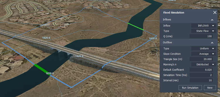
| Manning's coefficient (n) | Every triangle in the simulation area mesh is assigned a manning's n-value. You can choose between Uniform or Distributed depending on your project needs. Uniform: by default, the manning's n-value is set to .02 for every triangle in the flood simulation area. Distributed: if you have included coverage areas in your model to modify terrain or capture information about existing surface materials, any triangle in the flood simulation that overlaps a coverage area will be assigned a manning's n-value based on the visual material used in that coverage area style. These rules are mapped in the MaterialMapping2RunoffManningCoeff.clp file within C:\ProgramData\Autodesk\InfraWorks\Resources\Standards\Drainage\Common\Rules. You can edit this CLP file in a text-editing application. See To modify default manning's coefficient (n) values in the .CLP file. |
| Simulation time (hrs) | Specify total simulation time in hours. |
| Interval (min) | Specify interval length in minutes. |
- Click Run Simulation to run the flood simulation animation.