Dynamic Geometry Attributes work is primarily done directly in the Node Editor. The Attribute Editor is available for fine-tuning individual node parameters and inspecting attribute-level details. It is typically used when deeper control over calculation methods, normalization settings, or visualization parameters is needed.
dgaTension Node
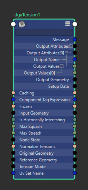
- Dynamic Geometry Attributes Tension
- The DGA Tension node calculates surface tension values by comparing an original mesh to a deformed mesh. It outputs per-element data representing squash and stretch, which can be used for visualization, analysis, or driving downstream rigging workflows.
- Input Geometry:The geometry being analyzed for tension calculations. Must match the topology of the Original Geometry to ensure accurate vertex-to-vertex comparisons.
- Reference Geometry: Optional geometry to compare against when calculating tension. If not connected, the Original Geometry will be used as the reference. Must match the topology of the Original Geometry.
- Original Geometry: Non-deforming base geometry, used similarly to a deformer's Original Geometry. Provides the topology data needed for tension calculations and serves as the reference if Reference Geometry is not connected.
- Tension Calculation
- Normalize Tensions: When enabled, tension outputs are clamped and scaled to a [0, 1] range based on the Max Stretch and Max Squash values. This provides consistent output ranges regardless of mesh scale or deformation intensity.
- Max Stretch:Maximum stretch value for clamping and normalization. Values are clamped to this limit even if normalization is disabled. Minimum value of 1 represents a 1:1 ratio (no stretch). Output values are clamped and normalized to this value minus 1.
- Max Squash: Maximum compression value for clamping and normalization. Values are clamped to this limit even if normalization is disabled. Minimum value of 1 represents a 1:1 ratio (no squash). Output values are normalized to this value minus 1.
- UV Set Name: Specifies the UV set to use for UV directional tension calculations. If left blank, the current active UV set is used. Only applicable when using UV-based calculation methods.
- Component Tag Expression: Expression for defining a subset of components to process. Works similarly to component tags in deformers. When processing subsets, outputs are generated as sparse arrays containing data only for the specified components.
- Output Data
- Output Attributes:
- Edge Mode:
- [0] Squash: Overall squash values per vertex showing how much attached edge lengths have shrunk compared to reference geometry.
- [1] Stretch: Overall stretch values per vertex showing how much attached edge lengths have expanded compared to reference geometry.
- UV Mode:
- [0] Squash U: Squash in the U-component direction based on UV mapping.
- [1] Squash V: Squash in the V-component direction based on UV mapping.
- [2] Stretch U: Stretch in the U-component direction based on UV mapping.
- [3] Stretch V: Stretch in the V-component direction based on UV mapping.
- Edge Mode:
- Output Geometry: Passthrough of the unchanged input geometry, provided for convenience in node graph connections. When connected, the tension node appears in the output mesh node's Deformation table.
Note: UV directional tension calculates UV basis vectors for each edge and maps tension values accordingly.
dgaDelta Node
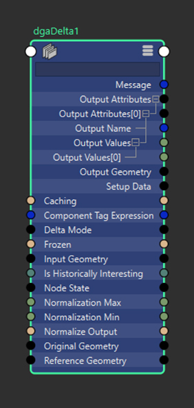
- Dynamic Geometry Attributes Delta
- The DGA Delta node calculates positional and normal differences between two meshes. It is used to measure how geometry has changed over time or between deformation states and outputs per-element delta data for visualization or further processing.
- Input Geometry: The geometry being analyzed for delta calculations. Must match the topology of the Original Geometry for accurate vertex-to-vertex comparisons.
- Reference Geometry: Optional geometry to compare against when calculating deltas. If not connected, the Original Geometry is used for comparison. Must match the topology of the Original Geometry.
- Original Geometry: Non-deforming base geometry providing topology data for calculations. Used as the reference geometry if Reference Geometry is not connected.
- Delta Calculation
- Normalize Output: When enabled, delta outputs are clamped and scaled to a [0, 1] range based on the Normalization Min and Max values.
- Normalization Min: Minimum value for clamping and normalization. Only applicable when normalization is enabled.
- Normalization Max: Maximum value for clamping and normalization. Only applicable when normalization is enabled.
- Component Tag Expression: Expression for defining a subset of components to process. Works similarly to component tags in deformers. When processing subsets, outputs are generated as sparse arrays containing data only for the specified components.
- Output Data
-
Output Attributes: Array of calculated output attributes with compound data containing names and per-vertex values. Contents depend on the calculation mode:
-
Position Mode:
- [0] PositionDelta: Overall magnitude of each vertex's positional change in object space (always positive).
- [1] PositionDeltaX: Positional change in the X direction (may be positive or negative).
- [2] PositionDeltaY: Positional change in the Y direction (may be positive or negative).
- [3] PositionDeltaZ: Positional change in the Z direction (may be positive or negative).
-
Normal Mode:
- [0] Normal: Change in vertex normal direction, measured in degrees (ranges from 0 to 180 when not normalized).
-
Position Mode:
- Output Geometry: Passthrough of the unchanged input geometry for node graph convenience. When connected, the delta node appears in the output mesh node's Deformation table.
Note: Position component deltas (X, Y, Z) are normalized based on absolute values to a [-1, 1] range. For example, with min=0 and max=2, values [1, 2, 0, -2, -1] normalize to [0.5, 1, 0, -1, -0.5].
dgaVisualizer Node
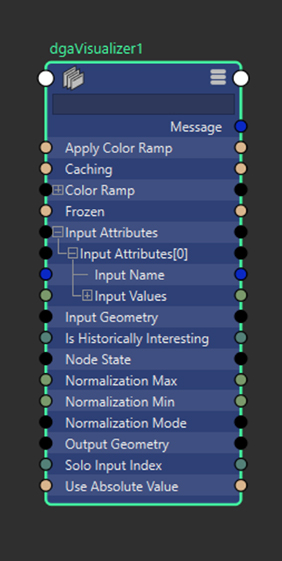
- Dynamic Geometry Attributes Visualization
- The DGA Visualizer node displays Dynamic Geometry Attributes data as vertex colors on a mesh. It is used to inspect deformation-related values such as tension, squash, stretch, or delta changes.
- Input Attributes: Dynamic Geometry Attributes data to visualize. Connect this to the Output Attributes of DGA calculation nodes. Multiple attributes can be connected and visualized.
- Solo Input Index: Specifies which input attribute to visualize. For example, when visualizing tension data, index 0 displays squash and index 1 displays stretch.
- Use Absolute Value: Displays the absolute value of incoming data. Negative values are visualized as positive values.
- Visualization Controls
-
Normalization Mode: Controls how input attribute values are normalized for visualization.
Mode Description Static (Default) Uses fixed minimum and maximum values. Values are clamped but not rescaled. Results are consistent across frames. Dynamic Computes minimum and maximum values from the current data and rescales values to the 0-1 range. Results may vary per frame. - Static: Uses Normalization Min and Normalization Max to define a fixed normalization range. Values outside the range are clamped.
The default range is 0 to 1. With default values, incoming data is clamped but not scaled.
Static normalization is recommended for animation playback and for comparing results across frames.
-
Dynamic: Determines the normalization range from the current input data. The minimum value is mapped to 0 and the maximum value is mapped to 1.
Dynamic normalization is sensitive to outliers and low-variance data and may produce different results per frame.
Note:- Use Static normalization for stable visualization across time.
- Use Dynamic normalization to inspect relative differences within a single frame.
- For data with negative values, enable Use Absolute Value or adjust Normalization Min and Normalization Max.
- Static: Uses Normalization Min and Normalization Max to define a fixed normalization range. Values outside the range are clamped.
- Normalization Min: Minimum expected value in point data, used for static normalization mode.
- Normalization Max: Maximum expected value in point data, used for static normalization mode.
- Apply Color Ramp: Boolean control determining whether point data maps to the color ramp (true) or displays as greyscale (false).
- Color Ramp: Color gradient used to map data values when Apply Color Ramp is enabled.
- Output
- Output Geometry: Copy of input geometry with vertex colors applied to the active color set based on point data and visualization settings. Colors must be enabled in the mesh's display colors attribute to be visible.
dgaToArray Node
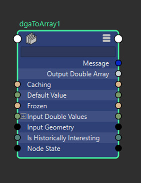
- Dynamic Geometry Attributes To Array
- The DGA To Array node converts Dynamic Geometry Attributes data into array attributes. This allows DGA data to be consumed by other Maya nodes, deformers, or rendering workflows that require array-based input.
- Arnold Integration
- Input Geometry: Geometry that the data applies to, determining the size of the output array.
- Input Double Values: Sparse array of Dynamic Geometry Attributes data to be converted to Arnold-compatible format.
- Default Value: Double value used to fill missing data when point data doesn't cover the full vertex count, ensuring complete arrays for Arnold.
- Output
- Output Double Array: Converted point data containing one value per vertex of the input geometry. Missing values from sparse input are filled with the default value.
Note: This node converts DGA data to the specific "doubleArray" attribute type required by Arnold for custom user data inputs. The data should be attached to a corresponding attribute on the display mesh using the naming pattern "mtoa_varying_[attr_name]" to make it available in Arnold through an aiUserDataFloat node.