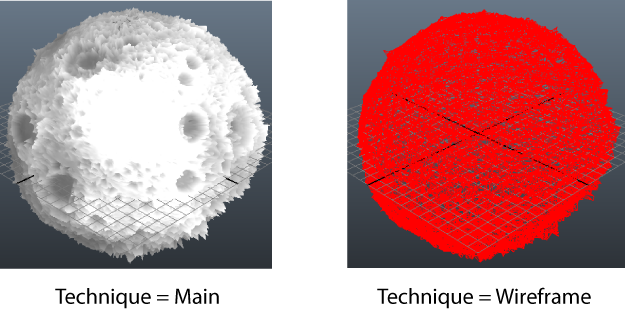
To write a custom GLSL shader, save it as a .ogsfx file. See the TessellationExample.ogsfx file in the ..\presets\GLSL\examples folder of the Maya installation for an example of how to write a GLSL shader that supports tessellation. The example demonstrates how to write the tessellation control shader, tessellation evaluation shader and geometry shader in the graphics pipeline.
In this shader, two techniques are defined: the main technique, which displays a shaded view, and the wireframe technique, which displays a wireframe that illustrates tessellation. To set the inner levels and outer levels of the tessellation, you can adjust the Inner levels/100*100 pix (the number of inner levels in a 100 x 100 pixels area) and the Outer levels/30 pix (the number of levels for every 30 pixels segment) settings and see the effect in Viewport 2.0.
Stages of the graphics pipeline
The Wireframe technique definition includes five stages of the graphics pipeline, and in the following order:
- vertex shader
- tessellation control shader
- tessellation evaluation shader
- geometry shader
- pixel shader
Tessellation shaders
See the GLSLShader ShaderTessControl section in the .ogsfx file for an example of how to create a tessellation control shader that generates an output patch by manipulating control points (cp) and that calculates the tessellation levels.
See the GLSLShader ShaderTessEval section in the .ogsfx file for an example of how to calculate the vertices for the corresponding domain generated by the primitive generator.
When performing tessellation in Maya, the tessellation control shader and tessellation evaluation shader require the input to be in PNAEN18 format. PNAEN18 (Point-Normal Triangles using Adjacent Edge Normals) creates indexing for each triangle with data such as: the vertex indices of the triangle, and the vertex indices of the triangle's adjacent and dominant edges. It creates a stride of 18 for the index array.
You must specify the input buffer type to be PNAEN18 in your technique definition:
string index_buffer_type = "GLSL_PNAEN18";
Geometry shader
The geometry shader is required to support wireframe and tessellation. The new primitives created by the tessellation shaders are regrouped by the geometry shader into triangles, which are subsequently drawn by the pixel shader.
Keywords to define your shaders in your technique
Use the following keywords to define your shaders:
- VertexShader
- TessControlShader
- TessEvaluationShader
- GeometryShader
- PixelShader
With each keyword, provide your input and output parameters and set the keyword to the name of your shader, for example, as follows:
VertexShader (in APPDATA, out SHADERDATA VS_OUT) = VS;
TessControlShader (in SHADERDATA TCS_IN, out TCSDATA TCS_OUT) = ShaderTessControl;
TessEvaluationShader (in TCSDATA TES_IN, out SHADERDATA2 TES_OUT) = ShaderTessEval;
GeometryShader ( in SHADERDATA2 GEO_IN , out SHADERDATA2 GEO_OUT ) = GS_Wireframe;
PixelShader (in SHADERDATA2 PS_IN, out pixelOut) = PS_Wireframe;
The input and output parameters can be of any data type that you define in the .ogsfx file.
