Channels for Computing and Following Trajectories
A channel is a simplified representation of the navigable space around a path from one place to another in a NavMesh. You can consider it as a kind of thick path such as, a road.
Channels have a straightforward structure that represents the navigable space in a simple manner. The information in a channel is easily accessible for computing trajectories that take care of constraints in the bot turning ability to anticipate the upcoming turns.
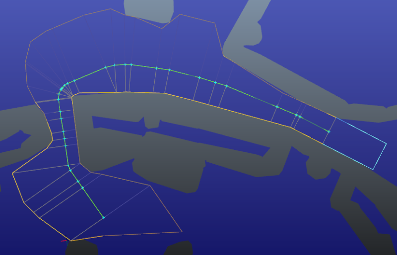
Channels are arrays of gates. The quad or triangle between two adjacent gates is called a channel section. Each section is completely free of any NavMesh obstacle. See the following figure:
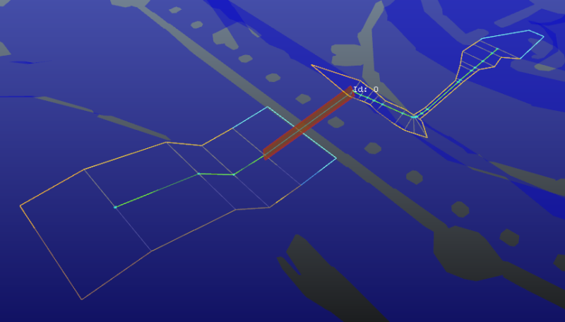
A path that goes through a NavGraph is associated with several channels. If enough space (width) is not available around the path to have a valid channel, the channel is split on the NavMesh. So, each NavMesh-laid part of the path can have more than one channel. All these channels are gathered into a ChannelArray that is aggregated into the path. See the following figure:
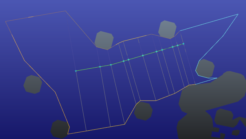
Channels have a pre-channel section and post-channel section. The pre-channel section and post-channel section are delimited with a counter clockwise open polyline. The counter clockwise open polyline is closed using the first gate or last gate. The pre-channel section and post-channel section are a prolongation of the first section and last section respectively. These sections are simplified polylines extracted from the NavMesh borders, so each position in the pre-channel section or post-channel section can see its orthogonal projection on the closure gate. See the following figure:
In a path without channels, a lower bound and an upper bound are computed to delimit the navigable part of the path according to dynamic changes in the NavMesh. The lower bound and upper bound are located on gate positions to make sure that all sections between the lower bound and upper bound are free of obstacles. If any obstacle collides with a section, it invalidates all sections. An obstacle that collides with the pre-channel section or post-channel section invalidates the first section or last section respectively.
You can create channels within path finding queries. When you use the functions in Kaim::Bot such as, Kaim::Bot::ComputeAStarQueryAsync or Kaim::Bot::InitAStarQuery to launch path finding queries, channels are automatically computed if the bot trajectory mode is Kaim::TrajectoryMode_Spline. If you initialize and launch path finding queries, you can enable channel computation using the SetComputeChannelMode function. The query enters ChannelArray computation stages that build a new channel around each refined path portion on a NavMesh. The original path is then replaced with the aggregation of channels and NavGraph-based original path portions that are left unchanged.
Channels are computed by gathering the free space around the original refined path. After the available free space is found, a radius-adaptive string pulling finds the mandatory turns considering the maximum free space in these corners. This determines the turn gates of the channel. Intermediary gates are then added when there is a long distance between turns to enlarge the available space wherever possible, which is used to find wider turns in the trajectory.
The SDK comes with a SplineTrajectory component that maintains and follows a circle-arc-based spline fitting the channel. This CircleArcSpline consists of circle arcs (magenta) and segments (cyan). See the following figure:
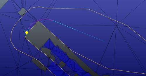
The spline is optimized to let a preferred distance to corners on each side and to lie on circles of preferred radii. However, when the channel is too constrained, these are released and the spline is left unchanged (sub-optimal) at these places.
The spline is recomputed if it is in the degraded mode (SplineComputation_Degraded). If the spline is not recomputed, the tail of the current spline is not modified over a given distance (5m, by default) when updating the channel trajectory. This provides a frame to frame stable trajectory that anticipates the upcoming turns. You get precise and stable information with SplineTrajectory to feed the animation system for an animation driven locomotion of your bots.
You can access the spline to know the current bot position on the spline and how the spline is computed. See the following example:
Kaim::ITrajectory* trajectory = m_bot->GetTrajectory(); //The bot has no trajectory, if it does not have a path.
Kaim::FollowedCircleArcSpline* followedSpline = trajectory-> GetFollowedCircleArcSpline(); // Give the following information.
followedSpline->m_spline;// Previously, trajectory->GetSpline()
followedSpline->m_positionOnSpline; //Previously, trajectory->GetPositionOnSpline()
followedSpline->m_computationMode
Following are the spline computation modes:
- SplineComputation_Optimal – All constraints are taken into account while computing the spline in a channel.
- SplineComputation_SubOptimal – All constraints are not considered while computing the spline in a channel.
- SplineComputation_Degraded – The spline is not computed properly, so it is generated from ShortcutTrajectory.
SplineComputation_Frozen – The spline is not recomputed, but can be cut where it goes out of the NavMesh, if BotConfig::m_trajectoryFailureMode is TrajectoryFailureMode_Safe. If set to TrajectoryFailureMode_Unsafe, the spline that is computed previously is followed as is. In this case, the bot can go out of the NavMesh or into excluded NavTags. NoteThe upper bound of a path is in the stability distance of the spline. To avoid jittering or stop and start behavior of the bot while transitioning to a new path, the spline is not updated when the upper bound is moved on the path.
- SplineComputation_OutOfNavMesh – The bot is going out of the NavMesh. The spline is generated from ShortcutTrajectory.
SplineComputation_Failure – The spline computation has failed. The shortcut cannot reach the path, and the bot is stopped.
To know if a path has to be recomputed, you do not need to check the spline computation mode. You can call m_bot->IsPathRecomputationNeeded() to know if a path must be recomputed.
Note: The trajectory can return a velocity even when IsPathRecomputationNeeded() returns true. For example, consider a spline whose computation mode is SplineComputation_Frozen. The path must be recomputed, but the trajectory still follows the spline while the path is computed. Additionally, IsPathRecomputationNeeded() can also return true when the trajectory is in TrajectoryMode_Shortcut.
You can define the minimal distance of a spline from the inner corners of a turn in a narrow channel using the DistanceToInnerCorner() function.
Previously, a float parameter (distToBorder) was used for computing the distance from the borders. When channelWidth was too small (less than two times of distToBorder), this distance was relaxed so that the spline passes about midway through a narrow channel. Now, you can customize this relaxation by defining a piecewise continuous affine function that gives the distance between the spline and the corners in the inner side of turns as a function of channelWidth. This function representation is a polyline that starts at (0,0), passes through several points, and becomes constant after the last point. It is parameterized by providing the polyline points [p0 to pn]. The (0,0) point is not provided because the first segment is automatically taken from (0,0) to p0. The default value has just one point (0.4, 0.2) that acts like the single float distToBorder parameter with the default value of 0.2. It is linear with linear coefficient of 0.5 when channelWidth is [0, 0.4], and constant to 0.2m when channelWidth is greater than 0.4m.
Note: All points must respect y<=x/2 so that a position can be found within channelWidth. A position cannot be found within channelWidth, if the distance to the inner corners is greater than channelWidth/2.
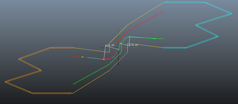
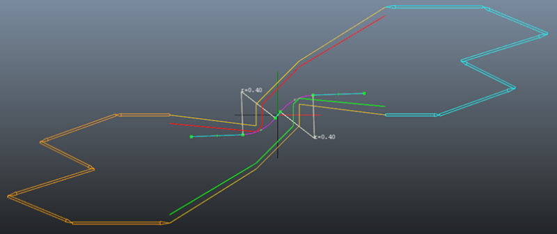
Typically, it is used for defining low linear coefficient (for example, y=x/10) sections for small channelWidth values and then rejoin y=x/2 somewhere at a maximal distance. See the following figures:
Default case – One point (0.4, 0.2). It is linear with a coefficient of 0.5 up to channelWidth = 0.4m and constant to 0.2m after that point.
Custom case – One point (1.0, 0.2). It is linear with a coefficient of 0.2 up to channelWidth = 1.0m and constant to 0.2m after that point.
Custom case - Two points: (0.3, 0.03) and (0.4, 0.2). It is linear with a very low coefficient of 0.1, and then takes a high step to join the constant value of 0.2m for channelWidth > 0.4m.
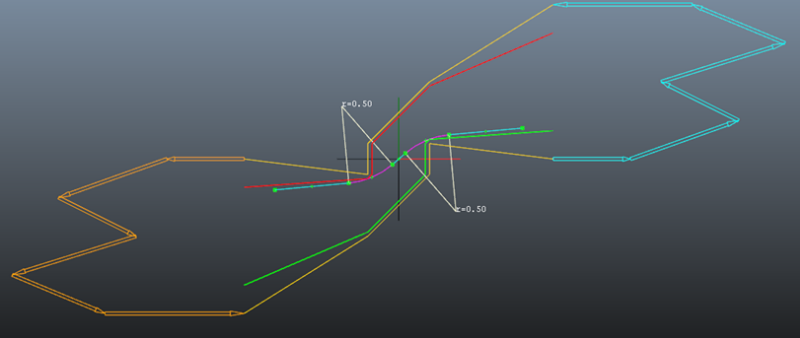
The red and green polylines are obtained by offsetting the channel borders with the corresponding distance to the inner corners.