About Rollers
A roller is used by a fiber placement machine to apply tows to a surface. You can create several types of rollers, each with their own characteristics and parameters. Adjust parameters to match the equipment you are using in your manufacturing environment. Most parameters are illustrated inside the Roller dialog box that opens when you add or edit a roller. Some of these illustrations are included here.
When you enter values in the roller dialog box, standard measurement units such as mm, in, ft (length) and N, lbf (force), are accepted. These are automatically converted into the default units of the current document.
Compressible Roller
A compressible roller is a single-segment roller that distributes its maximum compaction force over the entire roller. It is made of solid material, such as silicone, and is usually pliable, so that it compresses when pressed against a surface.

Edit segmented roller parameters in the Roller dialog box.
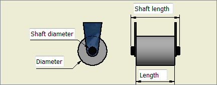
Diameter
The diameter of the roller.
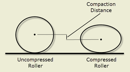
Compaction Distance
The maximum distance that the center of the roller can move when it is compressed against a surface.

It is important to know the position of the center of the roller because it affects the normal vectors of the NC points and helps eliminate poor compaction situations. All rotation of normal vectors is done around the center of the roller. Compaction distance is also critical for any rotations done for collision avoidance as well.
Shaft Length
The length of the shaft on which the roller is mounted. This should be longer than the length of the roller itself.
Shaft Diameter
The diameter of the shaft.
Compaction Force
The force, in Newtons (N), needed to compress the roller to its maximum compaction distance. The force is applied to the roller through the machine head. You can enter amounts in pound-force (for example, "100lbf") if you prefer, and it will be converted to Newtons.
Length
The length of the roller.
Mechanical Roller
A mechanical roller is a multi-segment roller that enables you to use different compression forces and distances for each segment. Each segment is attached by a spring.

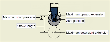
When a mechanical roller is resting against a surface, consider its starting position as its zero position. Since it is attached by a spring, it can be pushed upwards from the zero position into the machine as it rolls across a raised surface; for example, by 2 inches. This is its maximum compression. It can also extend downwards from the zero position as it rolls against a depressed surface (for example, 3 inches downward from the zero position). The total distance between its furthest extension downwards and its maximum compression upwards is called stroke length; for example, 2 + 3 inches equals a 5-inch stroke length.

Edit overall mechanical roller properties in the Geometry section of the Roller dialog box. Edit segment values in the Segments table of the Roller dialog box.
Diameter
The diameter of the roller.
Length
The length of the segment.
Stroke Length
The distance between the maximum upward extension and maximum downward extension.
Maximum Compression
The distance between the maximum upward extension and zero position. This is the maximum the roller can be pushed upward into the machine head.
Segmented Roller
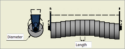
A segmented roller is a series of compressible rollers on one shaft.

Each segment can apply its own unique force to the surface. This is particularly useful on large convex or concave surfaces, where the outside segments are positioned downward (convex surface) or upward (concave surface) during application. For example, imagine applying material to an aircraft fuselage (a convex surface) in a direction parallel to the axis of the fuselage cylinder. You might want softer segments in the middle of the roller so they can compress more easily at the apex of the surface. You could have harder segments toward the edges, where the surface is further away from the roller axis. Using the wide application surface of a segmented roller is more efficient because it requires fewer passes over the surface.
Edit overall segmented roller parameters in the Geometry section of the Roller dialog box.
Diameter
The diameter of the segments.
Compaction Distance
The maximum distance that the center of a segment can move when it is compressed against a surface.

It is important to know the position of the center of the roller because it affects the normal vectors of the NC points and helps eliminate poor compaction situations. All rotation of normal vectors is done around the center of the roller. Compaction distance is also critical for any rotations done for collision avoidance as well.
Shaft Length
The length of the shaft on which the segments are mounted. This should be longer than the combined length of the segments.
Shaft Diameter
The diameter of the shaft.
In the Segments table of the Rollers dialog box, edit values for each segment of the roller.
Length
The length of a segment.
Compaction Force
The force, in Newtons (N), needed to compress the segment to its maximum compaction distance. The force is applied to the roller through the machine head. You can enter amounts in pound-force (for example, "100lbf") if you prefer, and it will be converted to Newtons. The sum of the compaction force of all the segments should equal the total compaction force required to compact the roller the desired compaction distance. The sum of the segment lengths should be smaller than the total shaft length.