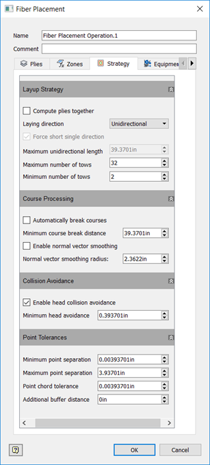
Strategy Tab
The Strategy tab determines how the plies are computed, the direction of the layup, and specific tow parameters on the paths. Edit values as needed to work with your equipment.
Layup Strategy
Compute plies together
Computes the plies as a single ply, essentially merging the boundaries of the plies together.
Layup Direction
- Unidirectional: The courses all travel in the same direction.
- Bidirectional: Every other course is reversed and travels in the opposite direction.
Force Short Single Direction
If layup direction is set to bidirectional, this option enables you to prevent courses from being reversed if the courses are too short. Courses shorter than defined in Maximum Unidirectional Length will not be reversed.
Maximum Unidirectional Length
If Force Short Single Direction is selected, this value is the maximum length of a course that should not be reversed when layup direction is set to bidirectional.
Maximum Number of Tows
The largest number of tows allowed for a course.
Minimum Number of Tows
The smallest number of tows allowed for a course.
Course Processing
Automatically Break Courses
If a course has a range along it where no tows are laid longer than the Minimum Course Break Distance, TruFiber breaks the course into smaller courses.
Enable Normal Vector Smoothing
Smooth vector transitions in cases where there are sharp changes in normal vector angles. Autodesk recommends that you set the Normal Vector Smoothing Radius to between one and three times the roller radius.
Collision Avoidance
Enable Collision Avoidance
If the distance between the part and the outer limit of the R value of a collision point is smaller than Minimum Head Avoidance value set here, a collision is expected. Enable this to avoid collisions using settings in the Laying Points dialog box.
Point Tolerances
Minimum Point Separation
The minimum distance allowed between points in the tool path. No two consecutive points in the tool path will be closer together than this. This prevents point density from being too high and affecting performance.
Maximum Point Separation
The opposite of Minimum Point Separation, this is the maximum distance allowed between points in the tool path. No two consecutive points in the tool path will be further than this distance from each other. This ensures that there is at least a certain density of points.
Point Chord Tolerance
The maximum distance allowed between the true tool path and the segment path between two points.
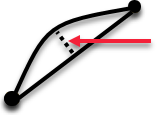
This works with minimum and maximum point separation to define a varying density of points to accentuate areas where there is discontinuity in tangency, such as a ramp. This is the reason that Minimum Point Separation is necessary, because Point Chord Tolerance may produce points that are too close together, depending on what the geometry is and what the chord tolerance is.
Additional Buffer Distance
The size of additional buffer area around the ply used to make sure that the tool path follows the surface.