Document Settings Reference
- Click Document Settings on the TruFiber ribbon.
Use the Document Settings dialog box to set default values for the current document. This dialog box contains most, but not all of TruFiber’s settings; for settings not included, the most recently-used values are used when working in TruFiber.
Toolpath Display Tab
Adjust color, style, and weight for parameters in the Toolpath Display tab of the Document Settings dialog box.
Add/Cut Markers
The points in the toolpath where tow or tape is added or cut.
Zone Markers
These markers show the outlines for process zones. A process zone is an area where you want to use specific manufacturing parameters appropriate for the characteristics of that area.
Other Markers
Information to follow.
Tip Points
These points at the tip of the roller on the surface are used to determine machine motion and calculate collision avoidance and process parameters.
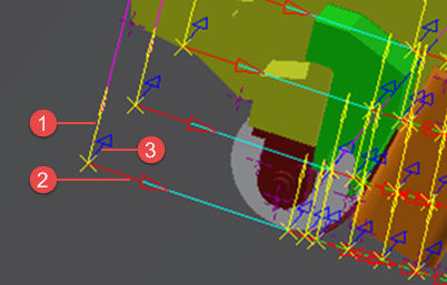
Tool, Tangent, and Roller Axes
These three axes types describe contact points and trajectories on the surface. By default, their size is set to 0, and you will not see them in the TruFiber window. To make them visible, set their sizes to values greater than 0, such as 1 inch.
- Tool axis: The vector that defines the normal to the contact point of the roller to the surface; in other words, the axis parallel to the axis of the head. When you rotate the head of the machine, you modify this vector.
- Tangent axis: The direction in which the material is laid down; in other words, the direction of the machine motion. These are at a tangent to tool axes.
- Roller axis: This axis is positioned at a laying or linking point and is parallel to the center axis of the roller. It is the third axis accompanying the tool and tangent axes at a contact point on the surface.
- Tool axis
- Tangent axis
- Roller axis
Laying Trajectories
These are the paths on the surface where the machine is laying material. Each line is at the center of a course; for example between tows 4 and 5 in an 8-tow course.
Roll In/Out Trajectories
These are the paths on the surface followed by the machine as it prepares to lay (roll in) or has finished laying (roll out) material. The machine roller makes contact with the surface, but no material is applied.
Retract Trajectories
These are paths followed by the machine as it retracts from the part after finishing a course. Motion for these paths is usually slower than when laying material.
Approach Trajectories
These are paths followed by the machine as it approaches the part to start a course. Motion for these paths is usually slower than when laying material.
Linking Trajectories
These are the off-part paths followed by the machine as it moves to the next course.
Break Ranges
A break range is an area of a course where no material is being laid down and the machine is still rolling on the surface. Break ranges are defined by the operation and can be automatically converted to off-part motion based on a minimum distance. There can be multiple gaps or ranges of course in a single toolpath. The break distances displayed in graphics should correspond with the break distances displayed in the Edit Courses dialog.
Fiber Path Display Tab
Adjust color, line style and weight, and other display options in the Fiber Path Display tab of the Document Settings dialog box.
Display Tow Edges
Show the edges of all tows.
Display Head Profiles
A head profile is a contact point (line) of the roller on the surface at each NC point. You can choose to display them at each tow cut (Outside Only).
Alternate Colors for Tow Edges
Use alternate colors for tow edges from course to course.
Tow/Course Edges
Set the color and line style to use for tow borders in each course.
Internal Tow Edges
Adjust line style and weight for the borders of all tows within courses. This uses the color set for Tow/Course Edges.
Alternate Colors for Tow Edges
Use alternate colors for tow edges from course to course.
Alternate Colors for Head Profiles
Use alternate colors back and forth from profile to profile.
Alternating Tow/Course Edges
Set an alternating color for tow/course edges. This would be the color used for every second course. This is only used if Alternate Colors for Tow Edges is selected.
Head Profiles
Adjust color and lines for head profiles.
Internal Head Profiles
If you are showing all head profiles, these are the properties of the inside, or internal, profiles at every NC point.
Alternating Head Profiles
Set an alternating color for head profiles. This would be the color for every second profile. This is only used if Alternate Colors for Head Profiles is selected.
Short Tow Areas
Adjust properties of tows that are too short to be manufactured, based on the minimum settings of your machine.
Surface Color
The color of the surface once layers have been added to it. This is not the same as the base surface. A toolpath has to be calculated based on the offset created by the added layers, and this setting enables you to see this offset when editing the toolpath.
Surface Edge Color
The edge color of the offset (layered) surface.