Working with Nesting Output
Nesting data is information in an output file that is used by nesting software, such as Autodesk TruNest, to optimize the amount of material used during the cutting process.
Create a Nesting Output File
- Make sure you have enabled and set up the manufacturing configuration you want to use for output.
-
Click Nesting
 on the TruPlan ribbon.
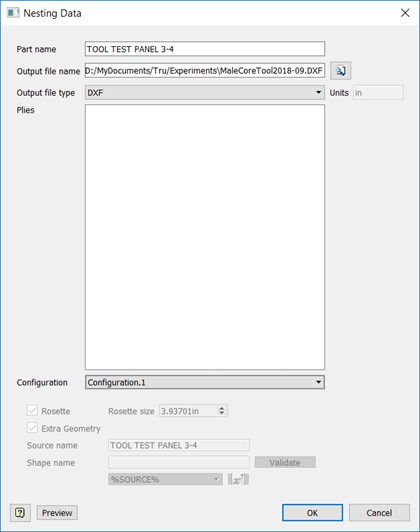
The Nesting Data dialog box opens.

The dialog box uses the most recently-used settings and options to generate a nesting data output file. The manufacturing configuration you are using determines which plies are included in the output, as well as the configuration settings shown at the bottom of the Nesting Data dialog box. If you want to change these settings, close the Nesting Data dialog box, modify your manufacturing configuration, then open the Nesting Data dialog box again.
-
Enter a Part Name for your model.
If you are creating a Composites Part Data file (CPD), the part name will be used as the assembly name in the file.
-
Enter a name and location for output.
You can set a default location in the Nesting Output tab of the TruPlan Options dialog box.
-
Select your Output File Type.
- DXF – The standard format for 2-dimensional geometry. This file format is compatible with software such as Autodesk AutoCAD, Fusion, and Inventor. The DXF output creates one or multiple files, depending on DXF Settings in the Nesting Output tab in TruPlan Options. for each material found in the composite model. The plies are separated and oriented so the flattened rosette’s primary direction is along the x-axis. Each ply is on a different layer. The ply name is placed in a text note within the ply geometry.
- TruNest Composites Part Data – TruNest proprietary file format (CPD file). This type of file can be read directly into TruNest to create ply geometry files and fill in the Part/Assembly table with information such as sub-assembly and part names.
Beside the Output File Type box, the default length unit is shown. This is set by the host application (for example, Inventor), and will be saved with your file.
-
Optional: Select a different manufacturing configuration from the Configuration box.
-
Click Preview to highlight the line segments and contours for cutting.
If there are plies in the manufacturing configuration that do not contain flat patterns (necessary for nesting), they are listed in an information box that opens.
-
Click OK to create the output file.
The output file is created in the folder you specified.
A report file of the same name with suffix -report.htm is also created. This report includes information such as which units and axis system were used, number of plies, information messages, geometry settings, and so on. This information can be useful when trying to recreate an output file later on.