
7. Select, Modify, and Duplicate Objects (AutoCAD Foundations)
During the design process, you will more often modify or duplicate objects than create new ones. The process involves selecting the objects to modify or duplicate. You can select the objects before or after starting the relevant command.
AutoCAD provides many ways to modify or duplicate objects to suit your needs.
The following video demonstrates some of the learning objectives covered in this topic:
Learning Objectives
- Prerequisites
- Prepare for the Exercises
- Erase Objects
- Select Multiple Objects
- Move and Copy Objects
- Rotate and Scale Objects
- Offset Objects
- Mirror Objects
- Trim and Extend Objects
- Fillet and Chamfer Objects
- Stretch Objects
- Grip Editing Objects
- Break and Join Objects
- Array Objects
- Explode Compound Objects
- Summary
- Related Commands
Prerequisites
You should know how to do the following before continuing:
- Create, open, save, and view drawings
- Work with commands
- Create basic 2D objects (lines and circles)
Prepare for the Exercises
To follow along with the exercises in this topic, download the ZIP file containing the sample drawings.
![]() Download: Sample drawing files used for the following exercises
Download: Sample drawing files used for the following exercises
The ZIP file contains all drawings used for the exercises and only needs to be downloaded once. Keep the ZIP file to restore the original state of the sample drawings.
Erase Objects
As work on a design progresses, some of the objects previously added will no longer be needed. These objects can be removed from the drawing.
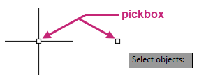
Before an object can be removed, it must be selected. An object can be selected by positioning the pickbox over an object and clicking. The pickbox, as its name suggests, is a box that appears at the center of the crosshairs when a command is not active or as a simple square cursor when being prompted to select objects while a command is active.
The selection of objects results in what is known as a selection set, which is the set of objects that will be acted upon by a command.
If you select objects before a command is active, you can press Esc to clear or deselect all selected objects.
The most recently erased objects can be restored with the OOPS command. So if you created or modified any objects after erasing objects, those erased objects can be restored without undoing other recent changes.
Try It: Erase Objects
Select individual objects and remove them from the drawing.
- On the Quick Access toolbar, click Open.Find
In the Select File dialog box, browse to the sample files you previously downloaded and select the Office Plan.dwg file. Click Open.
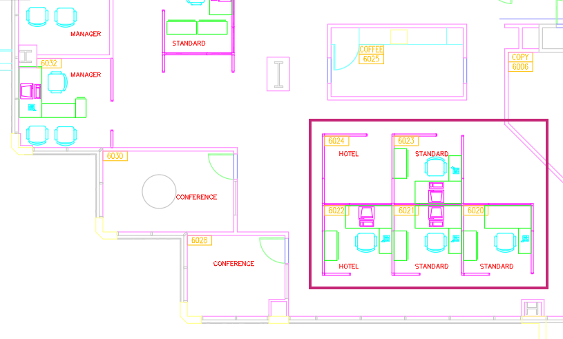
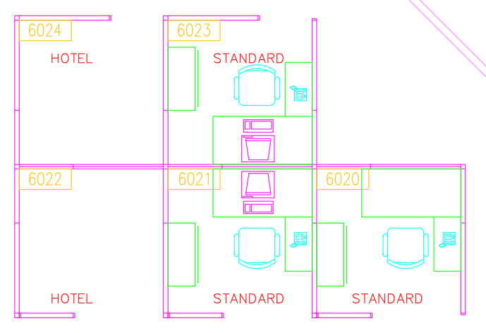
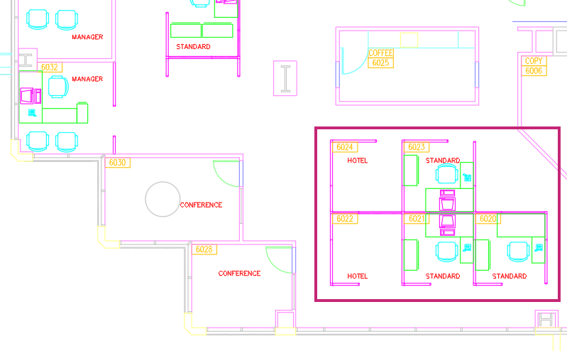
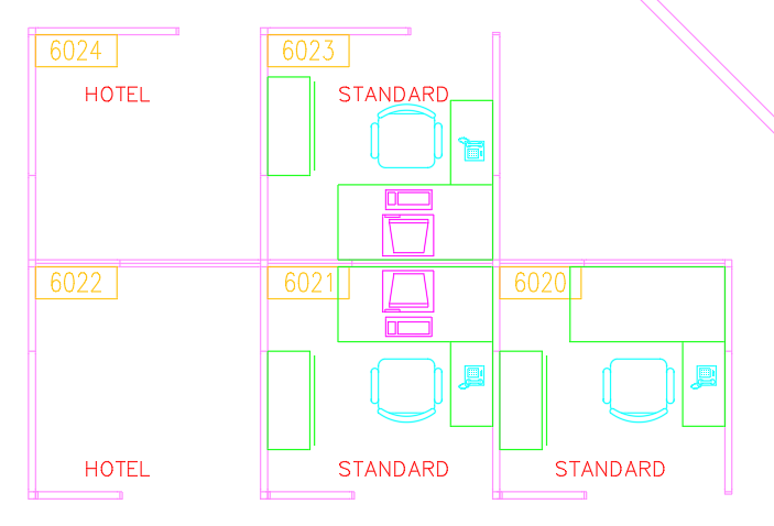
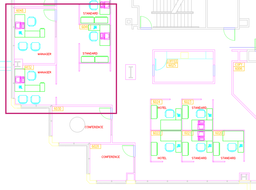
In the drawing, navigate to workstation 6022; it is located to the right of two conference rooms and among a pod of five workstations.
 Tip:
Tip:You can use the FIND command to find and replace text strings in a drawing.
- On the ribbon, click Home tab > Modify panel > Erase.Find
At the Select objects: prompt, position the pickbox cursor over the objects that represent a computer in the workstation and click.
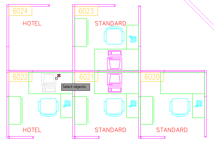
At the Select objects: prompt, continue selecting the desk, chair, phone, and file cabinet in the workstation.
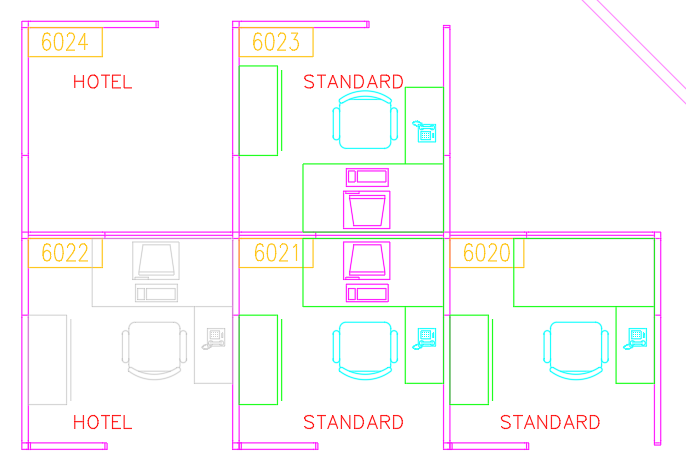
At the Select objects: prompt, press Enter to end object selection and erase the selected objects.
- On the Quick Access toolbar, click Save.Find
Don't close the drawing, as you will continue to use it in the next exercise.
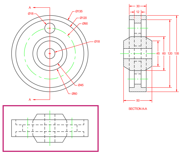
Select Multiple Objects
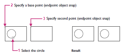
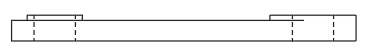
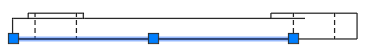
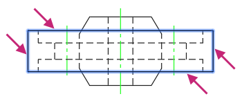
While you can select objects individually, you will often need to select multiple objects in an area. You can select multiple objects in an area by clicking an empty location (1), moving your cursor right or left, and then clicking a second time (2).
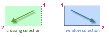
With a crossing selection, any objects within or touching the green area are selected.
With a window selection, only the objects completely contained within the blue area are selected.
When selecting objects in an area, the chances of selecting an object you didn't want to select increases. You can easily remove objects from a selection set. For example, if you select 42 objects, and two of them should not have been selected, hold down the Shift key and then select the two that you want to remove. Then, press Enter or the Spacebar, or right click to end the selection process.
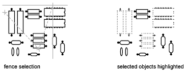
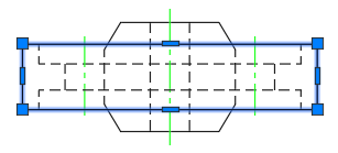
In addition to selecting objects individually or in an area, there will be times you want to select objects in an irregular shaped area or that are intersected by a path.
<need new images that show polygon and fence selections>
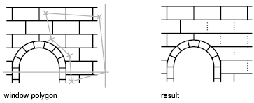
With a crossing polygon selection, any objects within or touching the green area are selected.
With a window polygon selection, only the objects completely contained within the blue area are selected.
With a fence selection, only the objects that intersect the path are selected.
Layers support the ability to be locked and unlocked. Locking a layer restricts objects on that layer from being selected.
Try It: Select Multiple Objects
Select multiple objects using window
and fence selection methods along with learning how locking a layer can
impact object selection.
If you closed or haven't opened the Office Plan.dwg sample file yet, open it now.
- On the Quick Access toolbar, click Open.Find
In the Select File dialog box, browse to the sample files you previously downloaded and select the Office Plan.dwg file. Click Open.
In the drawing, navigate to workstation 6022; it is located to the right of two conference rooms and among a pod of five workstations.
- On the ribbon, click Home tab > Modify panel > Erase.Find
At the Select objects: prompt, select any furniture in the workstation 6022 and press Enter, if the furniture exists.
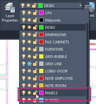
On the ribbon, click Home tab > Layers panel > Layers drop-down list and click the Unlocked Padlock icon adjacent to the PANELS layer.
The objects on the PANELS layer are now locked and cannot be selected.
- On the ribbon, click Home tab > Modify panel > Erase.Find
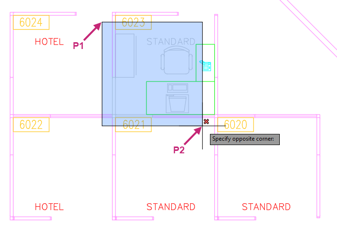
At the Select objects: prompt, position the pickbox cursor near P1 and click.
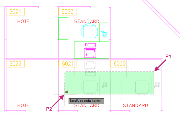
At the Specify opposite corner: prompt, move the cursor near P2 and click.
All objects within and that intersect the crossing window are selected except for the objects on the PANELS which are locked.
At the Select objects: prompt, press Enter to end object selection and erase the selected objects.
Press Enter again to repeat the ERASE command.
At the Select objects: prompt, position the pickbox cursor near P1 and click.
At the Specify opposite corner: prompt, move the cursor near P2 and click.
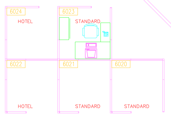
Only the objects within the window are selected, those that intersect with the window are not selected. Objects on the PANELS layer are also not selected because the layer is locked.
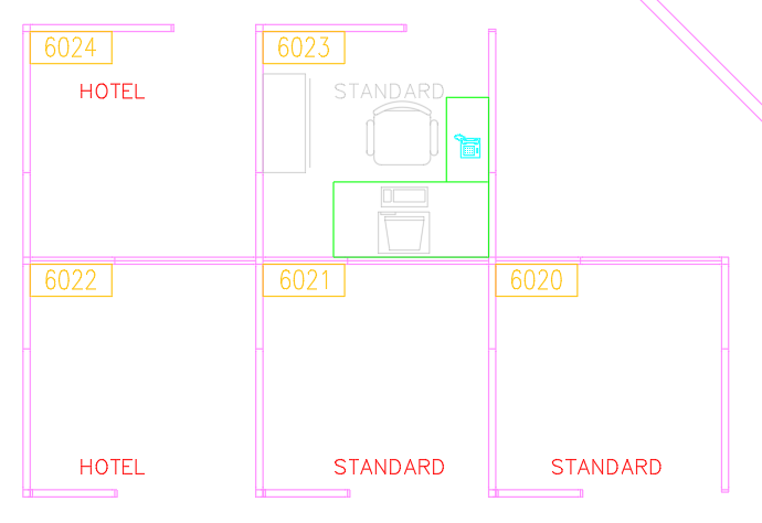
At the Select objects: prompt, select the desk and phone that weren't selected.
At the Select objects: prompt, hold down the Shift key and select the annotation with the text string STANDARD that was previously selected with the window selection.
The annotation is removed from the current selection set.
At the Select objects: prompt, press Enter to end object selection and erase the selected objects.
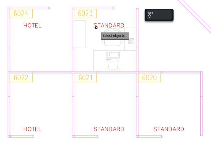
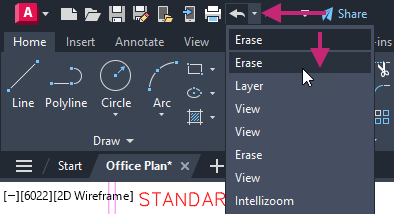
- On the Quick Access toolbar, click the Undo drop-down menu.Find
From the drop-down menu, position the cursor over the second Erase entry from the top and click.
This undoes the erasing of the most recent objects.
The furniture should still be removed from workstation 6022.
- On the Quick Access toolbar, click Save.Find
Don't close the drawing, as you will continue to use it in the next exercise.
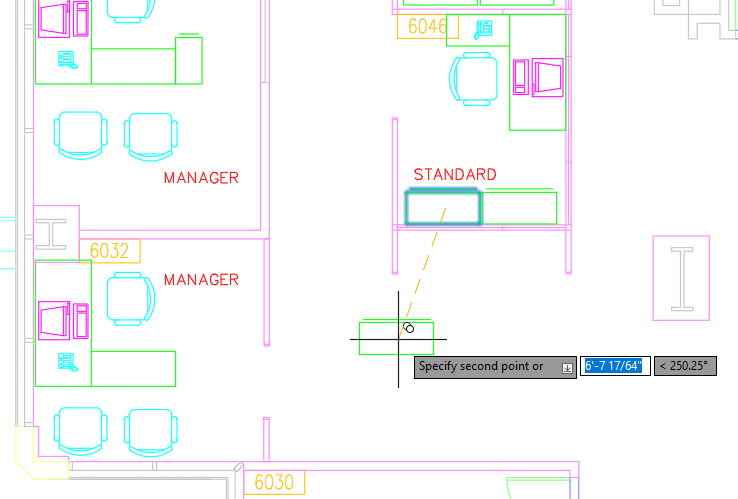
Move and Copy Objects
Repositioning objects in a drawing is one of the most basic ways you will modify objects. You reposition objects commonly by selecting the objects to be moved and then specify a base point (1) followed by a second point to determine the distance and direction of the move (2). In the illustration, these steps move the window higher and away from the door.
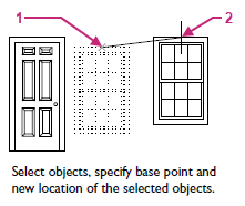
Along with repositioning objects, you will often want to duplicate and reuse parts of your design. You can duplicate objects by following the same process as used to reposition objects, select the objects you want to duplicate and then specify two points to define where the new objects should be created.
Try It: Move and Copy Objects
Move and copy objects within a drawing.
If you closed or haven't opened the Office Plan.dwg sample file yet, open it now.
- On the Quick Access toolbar, click Open.Find
- In the Select File dialog box, browse to the sample files you previously downloaded and select the Office Plan.dwg file. Click Open.
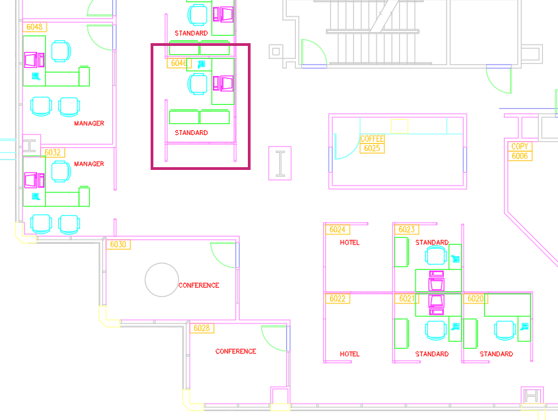
In the drawing, navigate to workstation 6046; it is located above the two conference rooms and among a row of five workstations.
- On the ribbon, click Home tab > Modify panel > Move.Find
At the Select objects: prompt, select the two file cabinets just above the annotation with the text string STANDARD and press Enter.
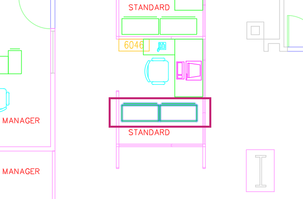
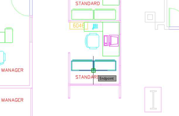
At the Specify base point or [Displacement] <Displacement>: prompt, hold down the Shift key and right-click.
- From the context menu, choose Endpoint.

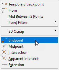
At the Specify base point or [Displacement] <Displacement>: _endp of prompt, specify one of the lower endpoints on the file cabinets.
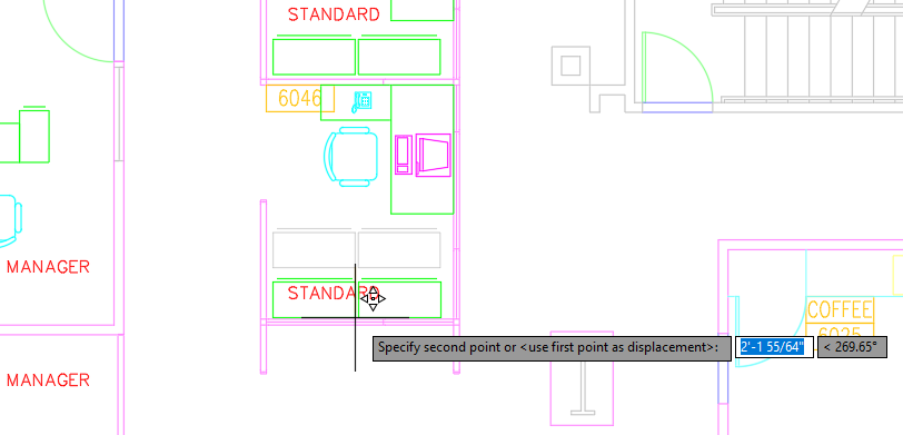
At the Specify second point or <use first point as displacement>: prompt, hold down the Shift key and right-click.
- From the context menu, choose None.

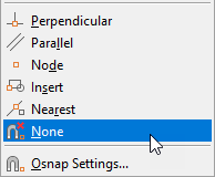
At the Specify second point or <use first point as displacement>: _non prompt, specify a point closer to the panels of the workstation.
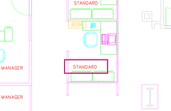
Press Enter to repeat the MOVE command and then reposition the annotation with the text string STANDARD above the file cabinets.
In the drawing, navigate to workstation 6022; it is located to the right of two conference rooms and among a pod of five workstations.
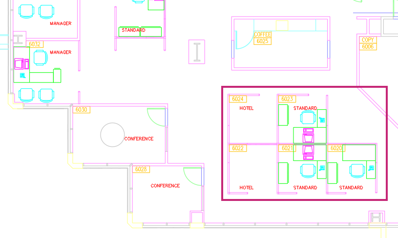
- On the ribbon, click Home tab > Modify panel > Copy.Find
At the Select objects: prompt, select all of the furniture in workstations 6023 and 6021 except for the computers. Press Enter to end object selection.
Remember:You can remove objects from a selection set by holding down the Shift key and selecting the objects to remove.
At the Specify base point or [Displacement/mOde] <Displacement>: prompt, hold down the Shift key and right-click.
- From the context menu, choose Endpoint.
At the Specify base point or [Displacement/mOde] <Displacement>: _endp of prompt, specify the lower endpoint on the panel's corner of workstation 6021.
At the Specify second point or [Array] <use first point as displacement>: prompt, specify the lower endpoint on the panel's corner of workstation 6022.
At the Specify second point or [Array/Exit/Undo] <Exit>: prompt, press Enter to end the command.
- On the Quick Access toolbar, click Save.Find
Don't close the drawing, as you will continue to use it in the next exercise.
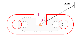
Rotate and Scale Objects
As you work on a design, the orientation of re-positioned or duplicated objects might need to be changed to align with adjacent objects in the design. You can change the orientation of selected objects by specifying a base point (1) followed by a second point to determine the rotation angle (2). In the following image, these steps change the orientation of a house.
By default, a positive angle results in a counterclockwise rotation. However, this setting can be changed as part of the drawing's units.
In addition to rotating objects, you may need to resize them. Do this using the same process as for rotating: select the target objects, then specify two points to define the scale factor for resizing.
Try It: Rotate and Scale Objects
Copy an existing object and then learn how to rotate and scale the copied object.
If you closed or haven't opened the Office Plan.dwg sample file yet, open it now.
- On the Quick Access toolbar, click Open.Find
- In the Select File dialog box, browse to the sample files you previously downloaded and select the Office Plan.dwg file. Click Open.
In the drawing, navigate to workstations 6032 and 6046; they are located above and to the left of the two conference rooms.
- On the ribbon, click Home tab > Modify panel > Erase.Find
At the Select objects: prompt, select the file cabinet next to the desk in workstation 6032. Press Enter to erase the file cabinet and end the command.
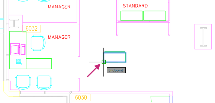
- Click Home tab > Modify panel > Copy.Find
At the Select objects: prompt, select one of the file cabinets in workstation 6046. Press Enter to end object selection.
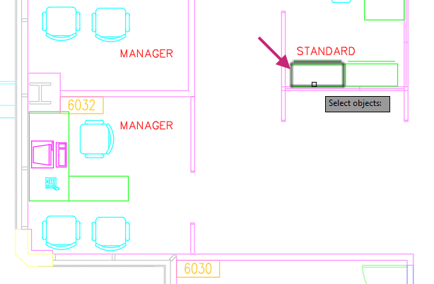
At the Specify base point or [Displacement/mOde] <Displacement>: prompt, specify a point on or near the selected file cabinet.
At the Specify second point or [Array] <use first point as displacement>: prompt, specify a point below and outside of workstation 6046.
Press Enter to end the COPY command.
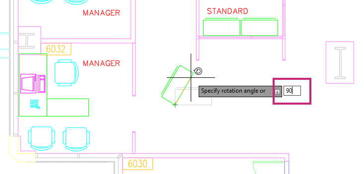
- Click Home tab > Modify panel > Rotate.Find
At the Select objects: prompt, select the copied file cabinet and press Enter to end object selection.
At the Specify base point: prompt, hold down the Shift key and right-click.
- From the context menu, choose Endpoint.
At the Specify base point: _endp of prompt, specify the lower-left endpoint on the file cabinet.
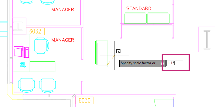
At the Specify rotation angle or [Copy/Reference] <0.00>: prompt, enter 90.
The file cabinet is rotated 90 degrees.
- Click Home tab > Modify panel > Scale.Find
At the Select objects: prompt, select the rotated file cabinet and press Enter to end object selection.
At the Specify base point: prompt, use the Endpoint object snap to snap to the lower-left endpoint on the file cabinet.
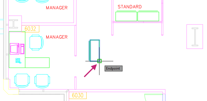
At the Specify scale factor or [Copy/Reference]: prompt, enter 1.15.
The file cabinet is scaled up to about 48" in length.
- Click Home tab > Modify panel > Move.Find
At the Select objects: prompt, select the resized file cabinet and press Enter to end object selection.
At the Specify base point or [Displacement] <Displacement>: prompt, use the Endpoint object snap to snap to the upper-right endpoint on the file cabinet.
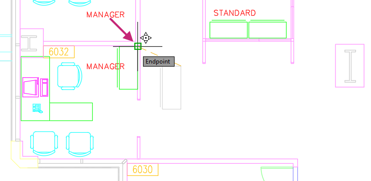
At the Specify second point or <use first point as displacement>: prompt, use the Endpoint object snap to snap to the endpoint inside of the upper panel of the workstation.
- On the Quick Access toolbar, click Save.Find
Optionally, close the drawing as you will use a different sample drawing in the next exercises.
Offset Objects
Many designs often contain parallel lines and curves, and concentric circles. Rather than calculating where these objects need to be created, you can create parallel and concentric objects by offsetting an existing object. Offsetting an existing object creates a copy of that object that follows the original object at a specified distance. This might result in an exact copy of the object, or an object that is shrunk or enlarged based on its distance from the original object.
Here is an example of offsetting a polyline.
Try It: Offset Objects
Offset lines and circles to create parallel and concentric objects to complete a design.
- On the Quick Access toolbar, click Open.Find
In the Select File dialog box, browse to the sample files you previously downloaded and select the Engine Mount.dwg file. Click Open.
- On the ribbon, click Home tab > Modify panel > Offset.Find
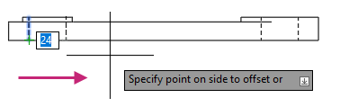
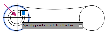
At the Specify offset distance or [Through/Erase/Layer] <Through>: prompt, enter 24.
At the Select object to offset or [Exit/Undo] <Exit>: prompt, select the line as indicated in the following image.
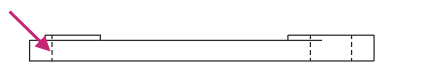
At the Specify point on side to offset or [Exit/Multiple/Undo] <Exit>: prompt, specify a point to the right of the selected object.
At the Select object to offset or [Exit/Undo] <Exit>: prompt, press Enter to exit the command.
Press Enter to repeat the OFFSET command.
At the Specify offset distance or [Through/Erase/Layer] <24.00>: prompt, enter 13.
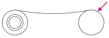
At the Select object to offset or [Exit/Undo] <Exit>: prompt, select the outer circle as indicated in the following image.
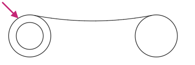
At the Specify point on side to offset or [Exit/Multiple/Undo] <Exit>: prompt, specify a point inside of the selected circle.
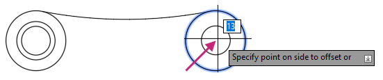
At the Select object to offset or [Exit/Undo] <Exit>: prompt, select the circle on the right.
At the Specify point on side to offset or [Exit/Multiple/Undo] <Exit>: prompt, specify a point inside of the selected circle.
At the Select object to offset or [Exit/Undo] <Exit>: prompt, press Enter to exit the command.
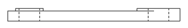
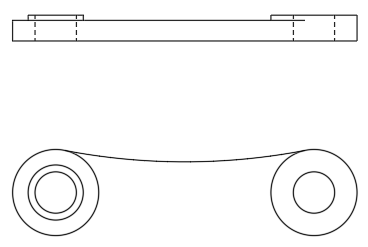
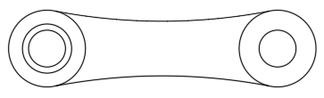
After offsetting the line and circles, the final design show look like the following image.
- On the Quick Access toolbar, click Save.Find
Don't close the drawing, as you will continue to use it in the next exercise.
Mirror Objects
Parts of a design are often symmetrical, such as mechanical parts or areas in an architectural building. Instead of drawing all symmetrical objects, you can draw half of the object and then mirror it.
To mirror objects, you define a mirror line with two points. You can then choose to delete or retain the original objects.
Here is an example of mirroring objects along a mirror line.
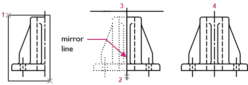
Always look for symmetry to save yourself extra work, even if the symmetry is not 100% identical.
Try It: Mirror Objects
Mirror an object along a mirror line to complete part of a design.
If you closed or haven't opened the Engine Mount.dwg sample file yet, open it now and make sure the previous related exercise was completed.
- On the Quick Access toolbar, click Open.Find
In the Select File dialog box, browse to the sample files you previously downloaded and select the Engine Mount.dwg file. Click Open.
Complete the Try It: Offset Objects exercise, if needed.
- On the ribbon, click Home tab > Modify panel > Mirror.Find
At the Select object: prompt, select the arc and press Enter to end object selection.
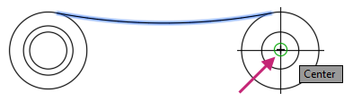
At the Specify first point of mirror line: prompt, hold down the Shift key and right-click.
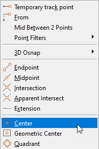
- From the context menu, choose Center.

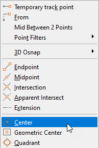
At the Specify first point of mirror line: _cen of prompt, specify the center of either circle on the right.
- On the status bar, click the Restrict Cursor Orthogonally button, if is not highlighted.FindTip:
You can press the F8 key to toggle Ortho mode on or off, or you can hold the Shift key down to temporarily toggle Ortho mode on or off while specifying a point.
At the Specify second point of mirror line: prompt, drag the cursor to the left to indicate the angle and direction of the mirror, and then click.
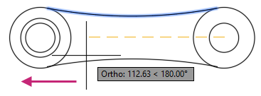
At the Erase source objects? [Yes/No] <No>: prompt, press Enter to keep the selected object.
- On the Quick Access toolbar, click Save.Find
Don't close the drawing, as you will continue to use it in the next exercise.
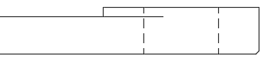
Trim and Extend Objects
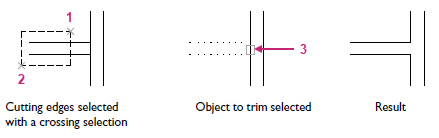
You can trim and extend objects so that they end precisely at a boundary defined by other objects. Trimming an object results in the shortening of an object, but it can also result in the removal of an object.
By default, when you trim or extend objects, all objects are defined as cutting or boundary edges must intersect the object to be trimmed or extended.
Try It: Trim and Extend Objects
Remove part of several objects by trimming them and extending an object to fix part of a design.
If you closed or haven't opened the Engine Mount.dwg sample file yet, open it now and make sure the previous related exercises were completed.
- On the Quick Access toolbar, click Open.Find
In the Select File dialog box, browse to the sample files you previously downloaded and select the Engine Mount.dwg file. Click Open.
Completed the Try It: Offset Objects and Try It: Mirror Objects exercises, if needed.
- On the ribbon, click Home tab > Modify panel > Trim/Extend drop-down menu > Trim.Find
At the Select object to trim or shift-select to extend or [cuTting edges/Crossing/mOde/Project/eRase]: prompt, select the right-side of the large circle on the left.
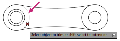
At the Select object to trim or shift-select to extend or [cuTting edges/Crossing/mOde/Project/eRase]: prompt, select the middle of the bottom line of the side view.
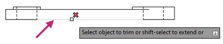
Press Enter to End the TRIM command.
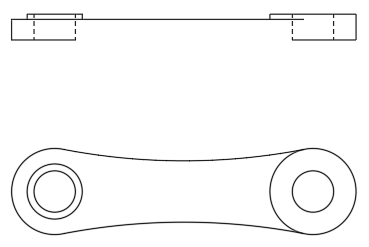
- Click Home tab > Modify panel > Trim/Extend drop-down menu > Extend.Find
At the Select object to extend or shift-select to trim or [Boundary edges/Crossing/mOde/Project]: prompt, select near the right endpoint of the bottom line on the left.
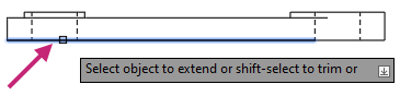
At the Select object to extend or shift-select to trim or [Boundary edges/Crossing/mOde/Project/Undo]: prompt, press Enter to end the command.
The line is extended to the next vertical line, but it remains as two separate horizontal lines. You can see this by selecting one of the bottom lines with no command active. Press Esc to deselect any selected object.
- On the Quick Access toolbar, click Save.Find
Don't close the drawing, as you will continue to use it in the next exercise.
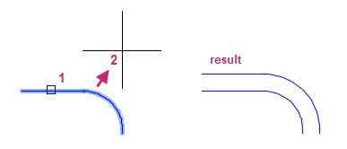
Fillet and Chamfer Objects
Filleting connects two objects with a rounded corner by creating an arc of a specified radius that is tangent to the selected objects. Chamfering, on the other hand, connects two objects with an angled line that intersects both objects based on an angle or two specified distances.
In the previous images, the middle shows the result of filleting two intersecting lines, and the right shows the result of chamfering the same two lines.
Lines are commonly the objects filleted or chamfered, but circles, arcs, and polylines can also be selected. More than one possible fillet can exist between circles and arcs, depending on where you select the objects.
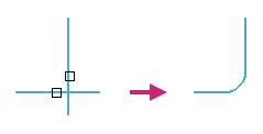
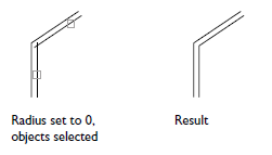
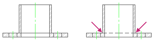
When working with designs that often have sharp corners, such as wall corners or angle brackets, you can create a fillet or chamfer with a radius or distance of 0. This technique allows you to quickly extend and trim lines to form a sharp corner, as illustrated in the following image. No arc or line is created. To do this, hold down the Shift key while selecting objects to fillet or chamfer to override the current fillet radius or chamfer distance with a value of 0.
Try It: Fillet Objects
Fillet multiple corners of a design.
If you closed or haven't opened the Engine Mount.dwg sample file yet, open it now and make sure the previous related exercises were completed.
- On the Quick Access toolbar, click Open.Find
In the Select File dialog box, browse to the sample files you previously downloaded and select the Engine Mount.dwg file. Click Open.
Completed the Try It: Offset Objects, Try It: Mirror Objects, and Try It: Trim and Extend Objects exercises, if needed.
In the drawing area, navigate to the left area of the side view, as indicated in the following image.
- On the ribbon, click Home tab > Modify panel > Fillet/Chamfer drop-down menu > Fillet.Find
At the Select first object or [Undo/Polyline/Radius/Trim/Multiple]: prompt, enter r.
At the Specify fillet radius <1.00>: prompt, enter 1.
At the Select first object or [Undo/Polyline/Radius/Trim/Multiple]: prompt, select the line indicated by (1) in the following image.
At the Select second object or shift-select to apply corner or [Radius]: prompt, select the line indicated by (2) in the previous image.
Press Enter to repeat the FILLET command.
At the Select first object or [Undo/Polyline/Radius/Trim/Multiple]: prompt, enter m.
This will set the FILLET command in Multiple mode which will allow you to continuously create fillets until the command is ended.
Added fillets to the corners indicated in the following image.
At the Select first object or [Undo/Polyline/Radius/Trim/Multiple]: prompt, press Enter to end the command.
- On the Quick Access toolbar, click Save.Find
Don't close the drawing, as you will continue to use it in the next exercise.
Try It: Chamfer Objects
Chamfer multiple corners of a design. Creating chamfers are similar to creating fillets.
If you closed or haven't opened the Engine Mount.dwg sample file yet, open it now and make sure the previous related exercises were completed.
- On the Quick Access toolbar, click Open.Find
In the Select File dialog box, browse to the sample files you previously downloaded and select the Engine Mount.dwg file. Click Open.
Completed the Try It: Offset Objects, Try It: Mirror Objects, and Try It: Trim and Extend Objects exercises, if needed.
- On the ribbon, click Home tab > Modify panel > Fillet/Chamfer drop-down menu > Chamfer.Find
At the Select first line or [Undo/Polyline/Distance/Angle/Trim/mEthod/Multiple]: prompt, enter a.
The Angle option is used to calculate the chamfer based on a distance on the first line and angle, and the Distance option can also be used to calculate the chamfer.
At the Specify chamfer length on the first line <0.00>: prompt, enter 1.
The distance is calculated from where the lines being chamfered intersect.
At the Specify chamfer angle from the first line <0.00>: prompt, enter 45.
The angle will be used to calculate the distance for the second line from the intersection.
At the Select first line or [Undo/Polyline/Distance/Angle/Trim/mEthod/Multiple]: prompt, enter e.
At the Enter trim method [Distance/Angle] <Angle>: prompt, enter a.
At the Select first line or [Undo/Polyline/Distance/Angle/Trim/mEthod/Multiple]: prompt, select the first line of the chamfer.
At the Select second line or shift-select to apply corner or [Distance/Angle/Method]: prompt, select the second line of the chamfer.
- On the Quick Access toolbar, click Save.Find
Don't close the drawing, as you will continue to use it in the next exercise.
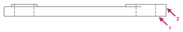
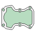
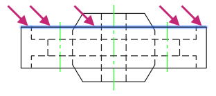
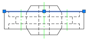
Stretch Objects
You can stretch most geometric objects, allowing you to lengthen or shorten parts of your model. For example, your model might be a gasket or the design for a public park.
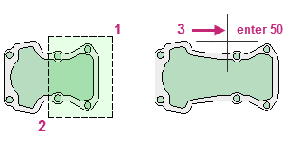
A crossing window is used to select the objects to stretch or move. Objects that are completely within the crossing window are moved, while those that are partially within the crossing window are stretched.
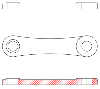
The following image shows the results of stretching geometry selected by a crossing selection (1 and 2) by a distance of 50 units. This distance might represent millimeters or feet. Notice that the small circles and the right-hand side of the shape are moved, while the objects crossed by the selection are stretched.
Try It: Stretch Objects
Lengthen objects of a design by stretching them.
If you closed or haven't opened the Engine Mount.dwg sample file yet, open it now and make sure the previous related exercises were completed.
- On the Quick Access toolbar, click Open.Find
In the Select File dialog box, browse to the sample files you previously downloaded and select the Engine Mount.dwg file. Click Open.
Completed the Try It: Offset Objects, Try It: Mirror Objects, Try It: Trim and Extend Objects, and Try It: Fillet Objects exercises, if needed.
In the drawing area, zoom to the extents of all objects.
- On the ribbon, click Home tab > Modify panel > Stretch.Find
At the Select objects: prompt, specify a point near (1) in the following image.
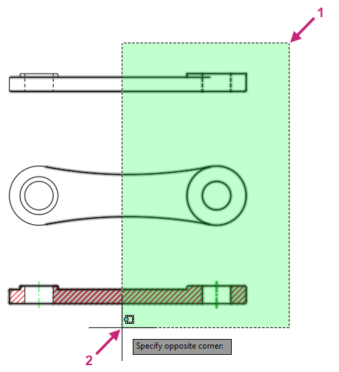
At the Specify opposite corner: prompt, specify a point near (2) in the following image.
At the Select objects: prompt, press Enter to end object selection
At the Specify base point or [Displacement] <Displacement>: prompt, specify a point near the selected objects.
- On the status bar, click the Restrict Cursor Orthogonally button, if is not highlighted.FindRemember:
You can press the F8 key to toggle Ortho mode on or off, or you can hold the Shift key down to temporarily toggle Ortho mode on or off while specifying a point.
At the Specify second point or <use first point as displacement>: prompt, move the cursor to the right.
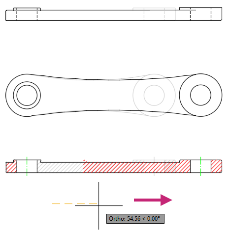
At the Specify second point or <use first point as displacement>: prompt, enter 25.
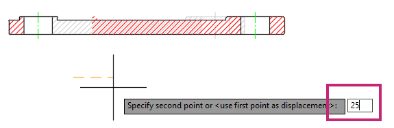
The objects that intersected the crossing window are stretched 25 units and those within the crossing window are moved 25 units to the right.
- On the Quick Access toolbar, click Save.Find
Don't close the drawing, as you will continue to use it in the next exercise.
Grip Editing Objects
Grips are displayed when you select an object without starting a command, most grips used for editing objects are square. Grips are often handy for light editing, such as stretching an object or moving a block based on its insertion point. For example, the line below accidentally snapped to the wrong endpoint. You can select the misaligned line, click on a grip and then click to specify the correct location.
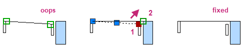
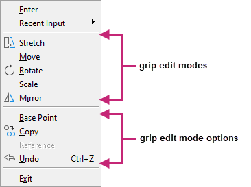
By default, when you click a grip, the grip editing **STRETCH** mode is activated. While grip editing is active, pressing Enter or the Spacebar cycles through several other editing modes. You can also change between grip editing modes and options using the context menu that can be displayed by right-clicking while a grip is clicked.
Some grips when you position the cursor over them display a menu of options. These grips are known as multifunctional grips. For information on these grips, see About Editing with Grips in the product help.
Try It: Use Grips to Edit an Object
Use grip editing to modify objects.
If you closed or haven't opened the Engine Mount.dwg sample file yet, open it now and make sure the previous related exercises were completed.
- On the Quick Access toolbar, click Open.Find
In the Select File dialog box, browse to the sample files you previously downloaded and select the Engine Mount.dwg file. Click Open.
Completed the Try It: Offset Objects, Try It: Mirror Objects, Try It: Trim and Extend Objects, Try It: Fillet Objects, and Try It: Stretch Objects exercises, if needed.
In the drawing area, zoom to the extents of all objects.
Press Esc a few times to make sure no command is active.
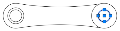
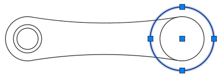
Select the inner circle on the right of the top view.
You should see five grips: one at each quadrant and one at the center point of the circle.
Click the right-most quadrant grip and move the cursor to the right.
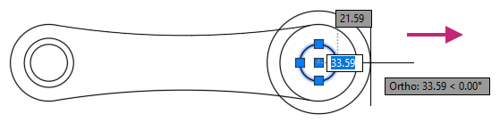
At the Specify stretch point or [Base point/Copy/Undo/eXit]: prompt, enter 36.
The radius of the circle is changed to 36 units from its original value of 12.
- On the Quick Access toolbar, click Undo.Find
The change to the circle's radius is undone.
Press Esc to make sure the circle is deselected.
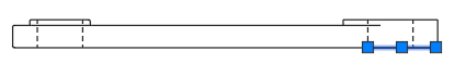
Select the line on the bottom right of the side view.
You should see three grips: one at each endpoint and one at the midpoint of the line.
- Press the Delete key or on the ribbon, click Home tab > Modify panel > Erase.Find
The selected line is removed. You are not prompted to select objects because an object was already selected before starting the ERASE command.
Select the remaining line on the bottom of the side view.
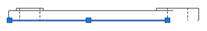
Click the right-most grip.
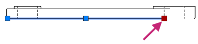
At the Specify stretch point or [Base point/Copy/Undo/eXit]: prompt, hold down the Shift key and right-click.
- From the context menu, choose Endpoint.
At the Specify stretch point or [Base point/Copy/Undo/eXit]: _endp of prompt, move the cursor to the right and specify the endpoint of the line.
Press Esc to deselect the line.
- On the Quick Access toolbar, click Save.Find
Optionally, close the drawing as you will work with a different sample drawing in the next exercises.
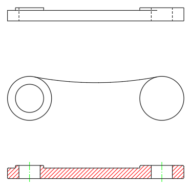
Break and Join Objects
There are times when you might want to break an object into two parts at a single point or between two points to create a gap. This is useful when a line or circle needs to be displayed with different linetypes. Breaking an object can be more efficient than trimming or erasing and redrawing objects. You can break most basic 2D objects, such as lines, arcs, circles, and open polylines.
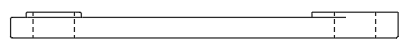
The following image shows an example of when you might break a line at two points, instead of redrawing the three lines separately.
Along with breaking an object, you can join collinear lines or convert an arc or elliptical into a circle or an ellipse. Joining objects reduces the number of objects in a drawing and can make changes easier.
Try It: Break and Join Objects
Break a line and change the layer of the new line along with join multiple lines to create a new line and then join multiple lines into a polyline.
- On the Quick Access toolbar, click Open.Find
In the Select File dialog box, browse to the sample files you previously downloaded and select the Pulley.dwg file. Click Open.
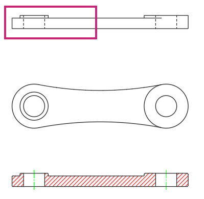
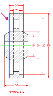
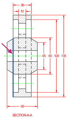
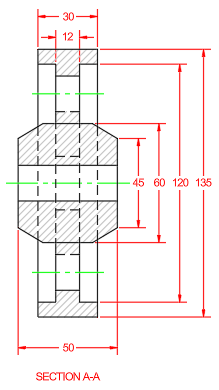
In the drawing, navigate to the section view as indicated in the following image.
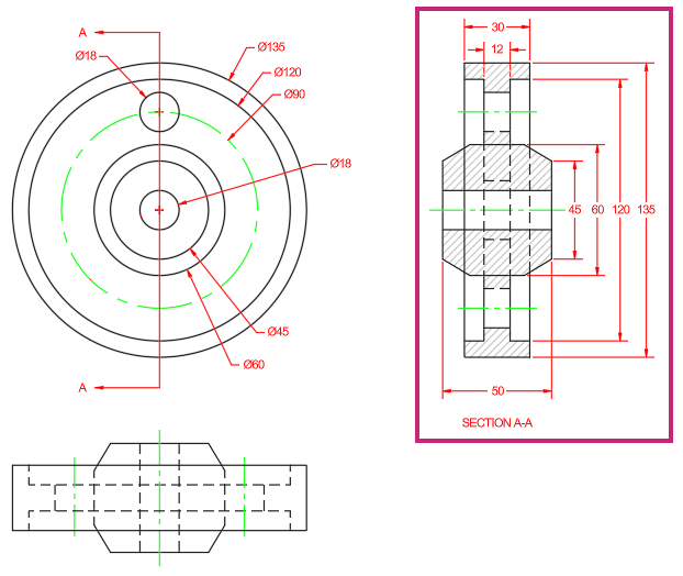
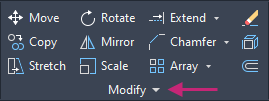
- On the ribbon, click Home tab > Modify panel (expanded) > Break at Point.Find
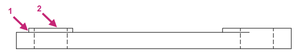
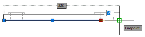
At the Select objects: prompt, select the vertical line near the point indicated in the following image.
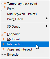
At the Specify break point: prompt, hold down the Shift key and right-click.
- From the context menu, choose Intersection.

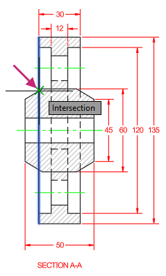
At the Specify break point: _int of prompt, specify the intersection as indicated in the following image.
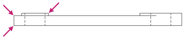
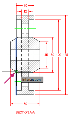
Press Enter to repeat the BREAKATPOINT command.
At the Select objects: prompt, select near the middle of the previously selected vertical line.
Notice the original line is now two lines.
At the Specify break point: prompt, specify the intersection as indicated in the following image.
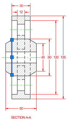
With no command active, select the previously selected vertical line.
Notice the original line is now three lines.
Press Esc to deselect the selected line.
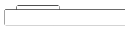
- On the ribbon, click Home tab > Properties panel > Match Properties.Find
At the Select source object: prompt, select the vertical line indicated by (1) in the following image.
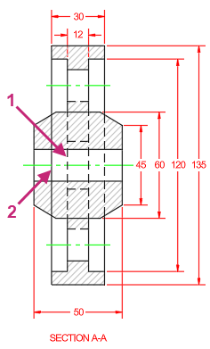
At the Select destination object(s) or [Settings]: prompt, select the vertical line indicated by (2) in the previous image and press Enter to end object selection.
The layer and other properties of the source object are assigned to the destination object, in this case the line created by breaking the original line twice. The new line should appear with a Hidden linetype.
- On the Quick Access toolbar, click Save.Find
Zoom to the extents of the drawing and navigate to the area of the side view as indicated in the following image.
- On the ribbon, click Home tab > Modify panel (expanded) > Join.Find
At the Select source object or multiple objects to join at once: prompt, select one of the five lines indicated in the following image.
At the Select objects to join: prompt, continue selecting the other four objects and press Enter to end object selection.
With no command active, select one of the lines indicated in the previous image.
Notice the five lines are now joined into a single object.
Press Esc to deselect the selected line.
Press Enter to repeat the JOIN command.
At the Select source object or multiple objects to join at once: prompt, select one of the four lines indicated in the following image.
At the Select objects to join: prompt, continue selecting the other three objects and press Enter to end object selection.
With no command active, select on one of the lines indicated in the previous image.
Notice the four lines are now joined into a single polyline object.
Press Esc to deselect the selected line.
- On the Quick Access toolbar, click Save.Find
Don't close the drawing, as you will continue to use it in the next exercise.
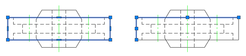
Array Objects
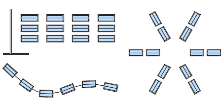
You can create copies of selected objects arranged in a pattern called an array. Arrays are helpful for creating repeatable patterns that are set a specific distance apart. For example, you can use arrays to create drill holes in a flange, teeth on a mechanical gear, building columns and office furniture layouts, or path of stepping stones in a landscaping project.
After selecting the objects you want to duplicate, known as the source objects, you choose the type of array to create. There are three types of arrays:
- Rectangular
- Path
- Polar
Here's what these arrays might look like when applied to arranging display tables:
Try It: Array Objects
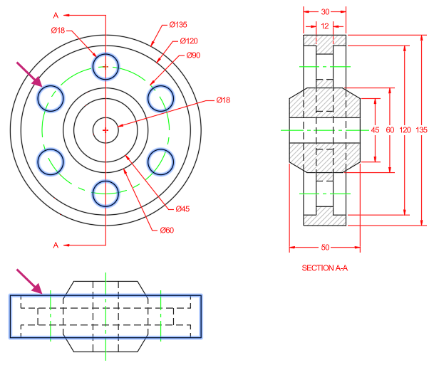
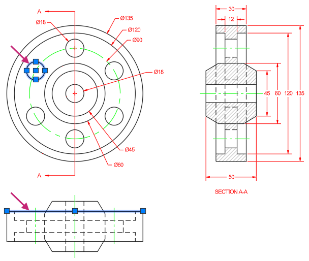
Create a polar array that results in six items. The source object for the array is a circle.
If you closed or haven't opened the Pulley.dwg sample file yet, open it now and make sure the previous related exercise was completed.
- On the Quick Access toolbar, click Open.Find
In the Select File dialog box, browse to the sample files you previously downloaded and select the Pulley.dwg file. Click Open.
Completed the Try It: Break and Join Objects exercise, if needed.
Zoom to the extents of the drawing and navigate to the area of the top view as indicated in the following image.
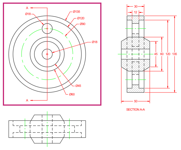
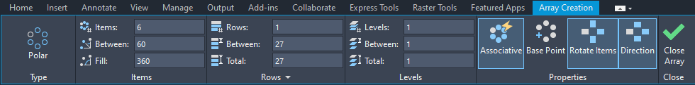
- On the ribbon, click Home tab > Modify panel > Array drop-down menu > Polar Array.Find
At the Select objects: prompt, select the circle indicated in the following image and press Enter to end object selection.
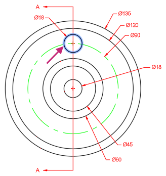
At the Specify center point of array or [Base point/Axis of rotation]: prompt, hold down the Shift key and right-click.
- From the context menu, choose Center.
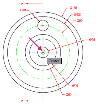
At the Specify center point of array or [Base point/Axis of rotation]: _cen of prompt, specify the center of the small circle at the center of the pulley in the following image.
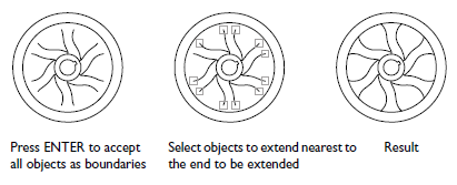
At the Select grip to edit array or [ASsociative/Base point/Items/Angle between/Fill angle/ROWs/Levels/ROTate items/eXit]<eXit>: prompt, press Enter to accept the default values.
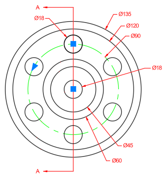
While creating the array, you can use the Array Creation tab to adjust the parameters of the array. After an array has been created, selecting an array will display the Array contextual tab on the ribbon and allow you to make changes to the array's parameters and edit the source object.
- On the Quick Access toolbar, click Save.Find
Don't close the drawing, as you will continue to use it in the next exercise.
Explode Compound Objects
Some objects within a drawing are compound which means they are made up of many individual elements such as lines, arcs, and other 2D objects or annotation. When a compound object is selected, the object can be modified using grips or specialized commands. There might be times when you need to edit the individual elements of a compound object, so when needed, you can break down a compound object into its simplified individual elements.
In the previous images, the left shows a selected polyline before it is exploded, and the right shows the result of the polyline being exploded with two of the segments selected.
Here are some of the common compound objects that can be found in a drawing:
- Polylines
- Multiline text (mtext)
- Dimensions
- Arrays
- Block references
Try It: Explode Objects
Break down an array and polyline into their simplified individual elements.
If you closed or haven't opened the Pulley.dwg sample file yet, open it now and make sure the previous related exercises were completed.
- On the Quick Access toolbar, click Open.Find
In the Select File dialog box, browse to the sample files you previously downloaded and select the Pulley.dwg file. Click Open.
Completed the Try It: Break and Join Objects and Try It: Array Objects exercises, if needed.
Zoom to the extents of the drawing.
- On the ribbon, click Home tab > Modify panel > Explode.Find
At the Select objects: prompt, select the objects indicated in the following image and press Enter.
Notice all the individual objects of the selected array and polyline compound objects are highlighted.
With no command active, select the same line and circle indicated in the previous image.
The circle and line are selected and not the array and polyline this time.
- On the Quick Access toolbar, click Save.Find
Optionally, close the drawing since this is the final exercise.
Summary
You learned the basics of how to select individual and multiple objects. Along with learning to select objects, most of the focus in this topic was on using many of the commands available to modify and duplicate existing objects rather than always needing to create new objects from scratch to complete a design. Knowing how and when to use the available modify and duplication commands will help to complete your designs with increased efficiency.
Related Commands
| Command | Description |
|---|---|
| ARRAY | Creates copies of objects arranged in a pattern. |
| ARRAYPATH | Evenly distributes object copies along a path or a portion of a path. |
| ARRAYPOLAR | Evenly distributes object copies in a circular pattern around a center point or axis of rotation. |
| ARRAYRECT | Distributes object copies into any combination of rows, columns, and levels. |
| BREAK | Breaks the selected object between two points. |
| BREAKATPOINT | Breaks the selected object into two objects at a specified point. |
| CHAMFER | Bevels or chamfers the edges of two 2D objects or the adjacent faces of a 3D solid. |
| COPY | Copies objects a specified distance in a specified direction. |
| ERASE | Removes objects from a drawing. |
| EXPLODE | Breaks a compound object into its component objects. |
| FILLET | Rounds or fillets the edges of two 2D objects or the adjacent faces of a 3D solid. |
| JOIN | Joins the endpoints of linear and curved objects to create a single object. |
| LENGTHEN | Changes the length of objects and the included angle of arcs. |
| MIRROR | Creates a mirrored copy of selected objects. |
| MOVE | Moves objects a specified distance in a specified direction. |
| OFFSET | Creates concentric circles, parallel lines, and parallel curves. |
| ROTATE | Rotates objects around a base point. |
| SCALE | Enlarges or reduces selected objects, keeping the proportions of the object the same after scaling. |
| SELECT | Places selected objects in the Previous selection set. |
| STRETCH | Stretches objects crossed by a selection window or polygon. |