Stretch existing connectors and add, move, and swap connector pins.
The Insert Connector toolbar has tools for modifying connectors and connector pins. You can also add, remove, or move the pins found inside of the connector.
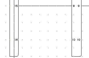
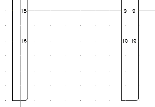
Stretch existing connectors
- Click
 . Find
- Respond to the prompts as follows:
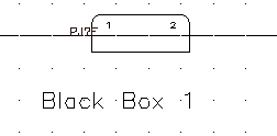
Specify which end of connector to stretch: Select the bottom of PJ1
Specify second point of displacement:
Pull the connector down towards the bottom of Black Box 1
- Repeat for PJ6, pulling the bottom of the connector down so that it is even with PJ1.
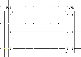
Add connector pins
- Click
. Find
- Respond to the prompts as follows:
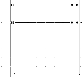
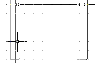
Select connector: Select PJ1
Specify where to insert new pin or [Reset]<16>:
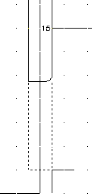
Select 4 spaces down from pin 15 on PJ1, right-click, and select Enter
The next available pin number (16) inserts at the selected point.
- Click
. Find
- Respond to the prompts as follows:
Select connector: Select PJ6
Specify where to insert new pin or [Reset]<10>:
Select the new pin 16 on PJ1 to insert pin 10 in-line with it, right-click and select Enter
 Note: You can delete pins using the Delete Connector Pins tool. Select the pin you want to delete and it is automatically removed from the connector.
Modify connector pins
- Click
. Find
- Respond to the prompts as follows:
Select connector pin to move: Select pin 16 on PJ1
Specify new location for pin 16: Select 2 spaces up on PJ1
Select connector pin to move: Select pin 10 on PJ6
Specify new location for pin 10:
Select pin 16 on PJ1 to move pin 10 in-line with it, right-click
- Click
. Find
- Respond to the prompts as follows:
Select connector pin: Select pin 16 on PJ1
Select connector pin: swap with: Select pin 12 on PJ1, right-click
- Click
. Find
- Respond to the prompts as follows:
Select connector to Reverse: Select the top in-line connector, right-click
- Click
. Find
- On the Insert Connector dialog box, specify:
Pin Spacing: 1.0
Pin Count: 2
Fixed Spacing
Pin List: 1
Insert All
- Click Details.
- On the Type section, select Add Divider Line.
- On the Display section, set Pins to Plug Side.
- Click Insert.
- Respond to the prompts as follows:
Specify insertion point or [Z=zoom, P=pan, X=wire crossing, V=horizontal/vertical, TAB=flip]:
Select to place the connector on the top of Black Box 1
- Click
. Find
- Respond to the prompts as follows:
Select connector to Rotate or [Hold]:
Select the new connector, right-click, and select Enter