
Defines the setup for the automatically generated PLC drawings. Setup includes the number and type of ladders, number and spacing of rungs, style, scale, and placement of modules, and placement and spacing for inline devices.
Find Command entry:
AESS2PLC
Command entry:
AESS2PLC
Choose the spreadsheet output file and click Open. In the Spreadsheet to PLC I/O Utility dialog box, click Setup.
List of Options
The following options are displayed.
Ladder
Controls that settings that relate to ladder configuration and placement.
- Origin
- Specifies the insertion point for the first ladder in the drawing. Corresponds to the upper left-hand corner of the ladder.
- Orientation
- Specifies whether to create a vertical bus ladder, with horizontal wires, or a horizontal bus ladder, with vertical wires.
- Reference numbers
-
Specifies the default referencing system:
- Numbers Only
- Numbers Ruling
- User Blocks
- X-Y Grid
- X Zones Note: Define and insert the X-Y Grid or X Zones on the drawing template or on each drawing after it is generated.
- Width
- Specifies the width of each ladder, the distance from left to right rail.
- Distance between
- Specifies the distance from the insertion point of one ladder to the insertion point of the next ladder. Vertical ladders insert from left to right. Horizontal ladders insert from top to bottom.
- Ladders per drawing
- Specifies the number of ladders to insert.
- Rungs per ladder
- Specifies the number of wire rungs in each ladder. This value multiplied by the rung spacing value determines the length of the inserted ladders.
- Rung spacing
- Specifies the distance from one rung to the next rung on a ladder.
- Rung count skip for I/O start
- Specifies the number of rungs to skip before inserting the first PLC module in a ladder.
- Suppression
- Specifies whether to include or exclude bus rails and rungs and whether to erase unused rungs.
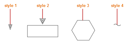
- Signal arrow style
- Specifies the wire signal arrow style. Select from the four predefined styles or a user-defined style.
Module
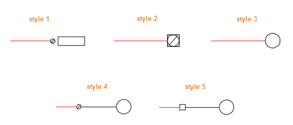
- PLC graphical style
- Specifies the default PLC module style. Select from the five predefined styles or a user-defined style.
- Input offset from neutral
- Specifies the insertion offset distance of the input module. For a vertical ladder, the offset distance is measured in the -X direction from the right vertical bus. For a horizontal ladder, it is measured in the +Y direction from the lower horizontal bus.
- Output offset from hot bus
- Specifies the insertion offset distance of the output module. For a vertical ladder, the offset distance is measured in the +X direction from the left vertical bus. For a horizontal ladder, it is measured in the -Y direction from the upper horizontal bus. Note: If the module type cannot be determined, or if it is a combination of input and output, then the module is inserted down the middle of the ladder.
- Maximum I/O per ladder
- Specifies the maximum number of module I/O points to insert into each ladder without breaking the module and continuing it in the next ladder.
- I/O point spacing
- Specifies the distance between I/O points on the module.
- Scale
- Specifies the scale factor for the PLC module, except for the I/O point spacing value defined previously.
In-Line Devices
- First input device from hot bus
- Specifies the starting offset distance from the left or upper bus for the first in-line device defined for each input module I/O point.
- First output device from neutral bus
- Specifies the starting offset distance from the right or lower bus for the first in-line device defined for each output module I/O point.
- Spacing between multiple devices
- Specifies the offset distance between the insertion point of one in-line device and the next one.
Spreadsheet/Table Columns
Displays a dialog box for reviewing and mapping spreadsheet columns to the attributes on the PLC module symbol, wire numbers, and the in-line devices.
Drawing Template
Specifies the drawing template file for new drawings. To use current template, leave the value blank. If you do not want to use a template, enter a single dot in the edit box.
Save
Saves the settings and spreadsheet information in a .wdi file to reuse.