
Use the Add Geometry tool in AutoCAD Electrical toolset to add the graphics to the block definition containing the previously added attributes.
Add Geometry Results:
- TAG1, TAG2, PLC TAG, and TAGSTRIP attributes are defined and selected first.
- The block definition is automatically modified.
- The color of the geometry changes by layer to distinguish what has been already converted as defined in the WD_M block.
Add geometry to the block
- Click
 . Find
- Respond to the prompts as follows:
Select block for additional geometry: Select 9PB
Select objects: Select the graphics for the push button, right-click
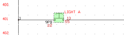
Specify insertion point: Select the middle of the push button
The geometry is associated to the template block files. Check that everything has been tied to the block by mousing-over 9PB. The text, wire connection attributes, description text, and geometry highlights.
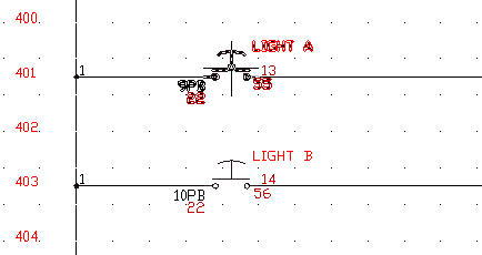
- Repeat steps 1 -2 for 10PB, 11PB, and 12 PB.
Your blocks are now AutoCAD Electrical toolset-smart.