
The program dynamically generates connectors based on the options selected at insertion time.
Reverse connector using the Tab key
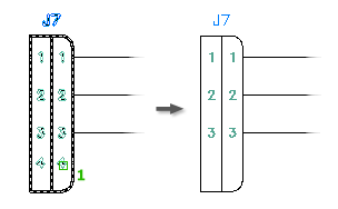
Prior to committing the connector outline to the drawing, you can press Tab to reverse the connector either about its long axis or end for end. If the connector is vertical, a series of TAB keystrokes cycles the image through these four orientations:
 |
 |
 |
 |
|
Start point |
TAB 1 |
TAB 2 |
TAB 3 |
Rotate connector using the V key
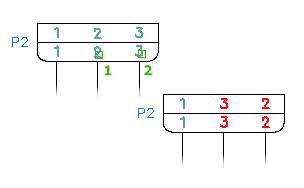
Press "V" at the command prompt to switch between vertical and horizontal orientations. Based on where the outline is in the flip process, the Tab keystroke reverses the connector either about its long axis or end for end. When in its horizontal orientation, a series of Tabs cycles the image through these four orientations
 |
 |
 |
 |
|
Start point |
TAB 1 |
TAB 2 |
TAB 3 |
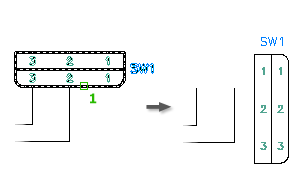
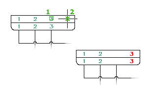
Switch layout using the X key
Press "X" at the command prompt to toggle between "Fixed Spacing" and "At Wire Crossings." Press the X key, and then move the connector preview over the wires so the connector stretches to align each pin with the underlying wire spacing. The connector stretches only to meet the underlying spacing when the first pin lands on a wire. If the size of the connector exceeds the total number of wires underlying the connector, the remaining pins follow the specified fixed spacing value.
The parametrically generated connector is a block with attributes. Tools are provided for modifying the connector block after insertion.
Rotate Connectors
Rotates a connector image in 90 degree increments.
Existing wire connections do not reroute with each rotation of the connector. Use the wire editing tools to resolve wiring.
Reverse Connectors
Reverses the connector image about its long axis.
Existing wire connections do not automatically reroute to the reverse side of the connector. Use the wire editing tools to resolve wiring.
Stretch Connectors
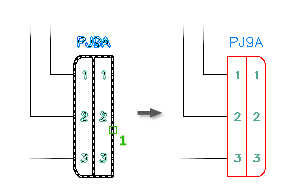
You can increase or decrease the overall shell length of the connector. Identify which end of the connector to alter and the measurement of displacement.
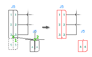
Split Connectors
Use this tool to split the parametric connector into two separate block definitions (for example, parent and a child or a child and another child).
You specify:
- Origin point for the new block
- Break type
- Layer for the child block
- Whether to reposition the child block
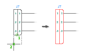
Add Pins to a Connector
Adds connector pins to an existing connector.
To make room for the new pins:
- Stretch Connector - stretch the connector shell
- Move Connector Pin - move existing pins
- Scoot - scoot wires with attached pins
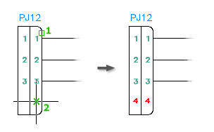
Delete Pins from Connectors
Deletes connector pins from an existing connector.
If the connector has a defined pin list, free this deleted pin for later insertion on this connector or on a related child of this connector.
Swap Pin Numbers
Swaps pin numbers on existing connectors.
Exchange one set of connector pin numbers for another on an existing connector or between connectors on the drawing.
Move pins
Moves the connector pin associated to a selected connector.
The pin relocates along the centerline axis of the connector, even if the pick point is off to one side of the connector. You can specify a location beyond either end of the current connector shell. Use Stretch Connector to extend the shell to enclose these pins.
Edit Connector Pin Numbers
Once the connector is inserted onto the drawing file's block definition, you can edit the connector pins found inside of the connector. Use the Connector Pin Numbers in Use dialog box to edit the pins defined on the parametric connector. Connector symbols have attributes to define Installation and Location codes, manufacturing data, component tagging and descriptions, and pin assignments.