
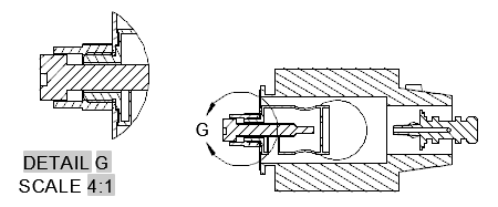
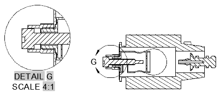
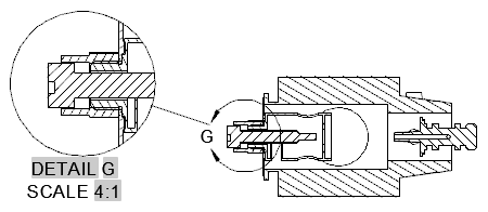
Creates a detailed view of a portion of an existing model documentation drawing view.
List of Options
The following options are displayed.
Representation Panel
This panel is visible only when you create a base view from an Inventor model. This panel is visible only when you are editing a detail view created from an Inventor model. The options you can view and edit depend on the properties of the selected model. In the editor mode, you can only edit the values for Design View.
Appearance Panel
- Hidden Lines
-
Specifies the display style to use for the selected detail view.
- Scale
-
Specifies the scale to use for the detail view. You can select a standard scale from the drop-down list, or directly enter a non-standard scale.
- Edge Visibility
-
Displays a list of objects to show in the detail view.
- Interference edges. Displays a line to show where two intersecting solid bodies meet.
- Tangent edges. Displays a line to show smooth edges formed by surfaces intersecting tangentially.
- Foreshortened. Shortens the length of tangential edges to differentiate them from visible edges.
- Bend extents. Displays sheet metal bend extent lines. Sheet metal bend extent lines indicate the location of transition about which a bend hinges or folds, in a flattened sheet metal representation.
- Thread features. Displays thread lines on screws and tapped holes.
- Presentation trails. Displays the lines (in drawing views from exploded views) that show the direction along which a components are moved into assembled position.
- Cut Inheritance
-
This option is disabled when creating a detail view.
- View Options
-
Displays the View Options dialog box. This dialog box specifies how to anchor the detail view being created, and how to display Inventor Reference Parts.
Boundary Panel
- Circular
-
Specifies that a circular boundary is used to create the detail view. This is the default boundary type.
If Infer Constraint is on, the center of the circular detail boundary is associated to a point on the parent view. If Infer Constraint is off, the center of the circular detail boundary is not associated to a point on the parent view.
- Rectangular
- Specifies that a rectangular boundary is used to create the detail view.
If Infer Constraint is on, the corner of the rectangular detail boundary is associated to a point on the parent view. If Infer Constraint is off, the corner of the rectangular detail boundary will not be associated to a point on the parent view.
Model Edge Panel
- Smooth
- Specifies that the edge of the detail view model is smooth.
- Smooth with Border
- Specifies that the edge of the detail view model is smooth with a circular or rectangular border, depending on the detail boundary type selected.
- Smooth with Connection Line
- Specifies that the edge of the detail view model is smooth, with a border, and connection line between the detail view and the detail boundary in the parent view.
- Jagged
- Specifies that the edge of the detail view model is jagged. There is no border for the detail view and no connection line between the detail view and the detail boundary in the parent view.

Annotation Panel
- Identifier
-
Specifies the label for the detail boundary and the resulting detail view.
- Show View Label
-
Specifies if the detail view label text is displayed.
Modify Panel
- Move
-
Moves the detail view, after it is placed in the drawing area, without forcing you exit the command.
Create Panel
- OK
-
Saves the changes and exits the Detail View Creation ribbon contextual tab.
- Cancel
-
Does not save the changes made, and exits the Detail View Creation ribbon contextual tab.