
List of Options
The following options are displayed.
Representation Panel
This panel is visible only when you are creating a section view from an Inventor model. The options you can view depend on the properties of the selected model. You can only edit the values for Design View.
Appearance Panel
- Hidden Lines
-
Specifies the display style to use for the selected section view.
- Scale
-
Specifies the scale to use for the view. You can select a standard scale from the drop-down list, or directly enter a non-standard scale.
- Edge Visibility
-
Displays a list of objects to show in the selected view.
- Interference edges. Displays a line to show where two intersecting solid bodies meet.
- Tangent edges. Displays a line to show smooth edges formed by surfaces intersecting tangentially.
- Foreshortened. Shortens the length of tangential edges to differentiate them from visible edges.
- Bend extents. Displays sheet metal bend extent lines. Sheet metal bend extent lines indicate the location of transition about which a bend hinges or folds, in a flattened sheet metal representation.
- Thread features. Displays thread lines on screws and tapped holes.
- Presentation trails. Displays the lines (in drawing views from exploded views) that show the direction along which a components are moved into assembled position.
- Cut Inheritance
-
Specifies if the view created out of a section view inherits the section cut.
- View Options
-
Displays the View Options dialog box. This dialog box specifies how to anchor the section view being created, and how to display Inventor Reference Parts.
Method Panel
The options in this panel are enabled only after the section view is placed in the layout.
- Projection View
-
Specifies the type of projection used to create the section view. You can create 2 types of projection views:
- Normal.
- Orthogonal.
- Depth
-
Specifies the depth of the section view.
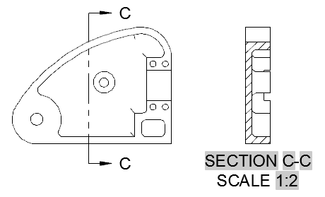
- Full. All geometry beyond the section line's cutting plane is included within the section view.
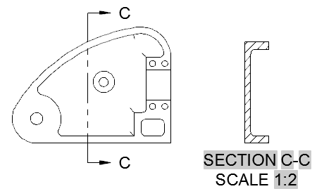
- Slice. All geometry beyond the section line’s cutting plane is removed from the section view and the section view represents a thin slice.
This option is available only after the section view is placed in the layout.
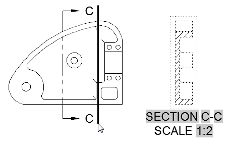
- Distance. The geometry between the section line’s cutting line and the distance specified is included within the section view. You can choose a point in the drawing, using the pointing device depth indicator line.
This option is available only after the section view is placed in the layout.
- Full. All geometry beyond the section line's cutting plane is included within the section view.
-
- Depth Distance
-
Specifies the depth distance, allowing the geometry beyond the section line's cutting plane to be included or removed from the section view.
This option is available only after the section view is placed in the layout and if the Distance option is selected in Depth.
Annotation Panel
- Identifier
-
Specifies the label for the section line and the resulting section view.
The program always determines from the drawing, the next free section label. Labels I, O, Q, S, X, and Z are excluded by default, however these can be manually overwritten. You can specify the alphabets to be excluded in the Modify Section View Style dialog box.
- Show View Label
-
Specifies if the section view label text is displayed for the current section view.
Hatch Panel
- Show Hatching
-
Specifies if hatch is displayed in the current section view.
Modify Panel
- Move
-
Moves the section view, after it is placed in the drawing area, without forcing you exit the command.
Create Panel
- OK
-
Saves the changes and exits the Section View Creation ribbon contextual tab.
- Cancel
-
Exits the Section View Creation ribbon contextual tab without saving the changes.