Creates and controls layout viewports.
Access Methods
Toolbar:
 Displays the view gallery.
Shortcut menu: Right-click the drawing area when a named layout is current and click New Viewport.
Summary
In a layout, you can create as many viewports as you want, but only up to 64 viewports can be active at one time (see MAXACTVP). Objects in model space are visible only in active viewports. Viewports that are not active are blank. Use the On and Off options to control whether viewports are active.
List of Prompts
The following prompts are displayed.
Specify corner of viewport or [ON/OFF/Fit/Shadeplot/Lock/NEw/NAmed/Object/Polygonal/Restore/LAyer/2/3/4].
Corner of Viewport
Specifies the first corner of a rectangular viewport.
On
Makes a selected viewport active. An active viewport displays objects in model space. The MAXACTVP system variable controls the maximum number of viewports that can be active at one time. If your drawing contains more viewports than the number specified in MAXACTVP, you must turn one off to make another one active.
Off
Makes a selected viewport inactive. Objects in model space are not displayed in an inactive viewport.
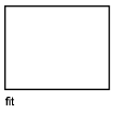
Fit
Creates one viewport that fills the layout to the edges of the printable area. When the paper background and printable area are turned off, the viewport fills the display.
Shadeplot
Specifies how viewports in named (paper space) layouts are plotted.
- As Displayed
-
Specifies that a viewport is plotted the same way it is displayed.
- Wireframe
-
Specifies that a viewport is plotted wireframe regardless of the current display.
- Hidden
-
Specifies that a viewport is plotted with hidden lines removed regardless of the current display.
- All Visual Styles
-
Specifies that a viewport is plotted using the specified visual style.
- All Render Presets
-
Specifies that a viewport is plotted using the specified render preset.
Lock
Prevents the zoom scale factor in the selected viewport from being changed when working in model space.
NEw
Creates and places a new view and layout viewport on the layout.
With this option, the drawing area switches temporarily to a maximized view of model space, where you can click two points to define the rectangular area of the view. This action creates an unnamed view within an appropriately sized layout viewport. Right-click to specify a different scale or click to place the layout viewport onto the current layout. The layout viewport is either set to a convenient default scale or set to the current annotative scale, and is locked. The scale can later be changed by unlocking the layout viewport and using the triangular scale grip.
NAmed
Inserts a named view that was previously saved in model space together with a new layout viewport onto the current layout. The layout viewport is either set to a convenient default scale or set to the current annotative scale, and is locked. The scale can later be changed by unlocking the layout viewport and using the triangular scale grip.
Object
Specifies a closed polyline, ellipse, spline, region, or circle to convert into a viewport. The polyline you specify must be closed and contain at least three vertices. It can be self-intersecting, and it can contain an arc as well as line segments.
Polygonal
Creates an irregularly shaped viewport using specified points.
- Arc
-
Adds arc segments to the polygonal viewport.
For a description of the options for creating arc segments, see the Arc option for the PLINE command.
- Close
-
Closes the boundary. If you press Enter after specifying at least three points, the boundary is closed automatically.
- Length
-
Draws a line segment of a specified length at the same angle as the previous segment. If the previous segment is an arc, the new line segment is drawn tangent to that arc segment.
- Undo
-
Removes the most recent line or arc segment added to the polygonal viewport.
Restore
Restores viewport configurations saved with the VPORTS command.
- Enter Viewport Configuration Name.
- ?
- First Corner
-
Positions and sizes new viewports using the window selection method; the viewports are fit into the selected area.
- Fit
-
Sizes the viewports to fill the drawing area.
Layer
Resets layer property overrides for the selected viewport to their global layer properties.
- Reset Viewport Layer Property Overrides Back To Global Properties. Enter Y to remove all layer property overrides.
- Select Viewports.
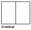
2
Divides the specified area horizontally or vertically into two viewports of equal size.
- Enter Viewport Arrangement.
- First Corner
-
Positions and sizes new viewports using the window selection method; the viewports are fit into the selected area.
- Fit
-
Sizes the viewports to fill the drawing area.
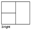
3
Divides the specified area into three viewports.
The Horizontal and Vertical options split the specified area into thirds. The other options split the area into three viewports: one large viewport and two smaller ones. The Above, Below, Left, and Right options specify where the larger viewport is placed.
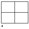
4
Divides the specified area horizontally and vertically into four viewports of equal size.