-
Click

 . Find
- On the Selection step of the wizard:
- From the View drop-down list, select Front.
- Select all the parts required to define a complete screw connection.
- Verify that the check boxes adjacent to the parts that must be visible for the front view are selected and the others are cleared.
- Select the nominal diameter for the screw connection.
- Click Next. The wizard hides.
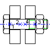
- Specify the insertion point (1).
- Specify the endpoint of the first hole (2).
- If you selected two holes in the Selection step of the wizard, specify the end point of the second hole (3). The Location step of the wizard displays.
- If there is a gap between the plates:
- Click
 under Gap. The wizard hides.
 - Click the end point of the first hole (2) and then the start point of the second hole (4).
- Click
 under GL2. The wizard hides.
 - Click the start point of the second hole (4) and then the end point of the second hole (3).
- Click
- Click Next. The Grip Representation step displays.
- Click the button that corresponds to the representation you need.
- Click Finish. The screw connection is inserted.