
Creates a feature identification symbol and attaches it to an object in the drawing area.
Find
Summary
You can specify up to two characters to identify a feature and also select the type of arrowhead to use at the end of the leader line.
List of Prompts
The following prompts are displayed.
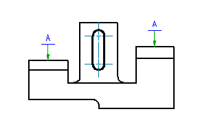
- Select object to attach
- Attaches the symbol to an object. To place the symbol without attaching it to anything, click the position you want to place the arrowhead of the leader. If you want to place the symbol without a leader, click the position you want to place the symbol.
- Start point
- Specifies the position of the leader arrow.
- Next Point
- Specifies the location of next vertex of the leader. Note: AutoCAD Mechanical toolset forces the first leader segment to be perpendicular to the attached object, and subsequent leader segments to be horizontal or vertical. To override this restriction, press the Toggle Symbol Leader Orthogonal Mode key (SHIFT + F, by default) as you move the cursor.
- Symbol
- Places the symbol at the most recently clicked location.