
An architectural project is the creation of a building from initial sketches to the realization of the building structure. A project in AutoCAD Architecture 2026 toolset is a set of linked drawing files containing all components necessary for the building project—building model geometry, section and elevation views, annotation, and plotting sheets.
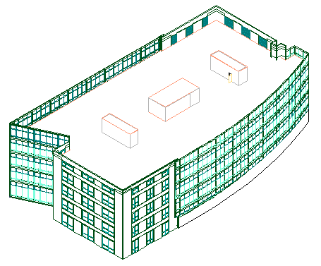
Building model in AutoCAD Architecture 2026 Toolset
Advantages of Working in a Project Environment
When you organize your building in an AutoCAD Architecture 2026 toolset project, you have the following advantages in your work:
- Organization of drawing and supporting files in one easily accessible location—Project Navigator
- Storage of project-based information such as the project name and number as well as site, utility, and financial data in a single location—Project Browser
- Updated sheet numbers to reflect changes made in the sheet set
- Notification of changes made to project drawings
- Control over project tools, project standard styles, and display settings
- Distribution of projects over a network with multi-user access
Project Components
A project consists of drawing files that represent different components in the design and documentation of the building model. There are drawings for individual parts of a building, like a single building level, or the framing components of a level. These drawings are referenced into more complex drawings, for example referencing all individual level drawings into one drawing displaying a complete view of the building model. From these view drawings, you can create other drawings for sections, elevations and annotated plot sheets for the project.
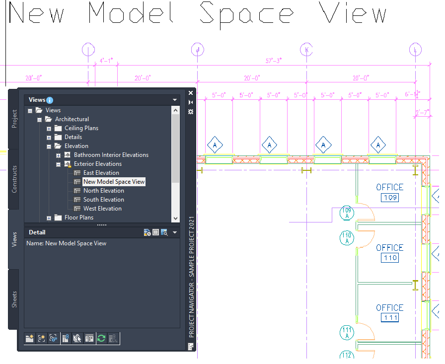
All drawings in the project are displayed and organized in the Project Navigator.
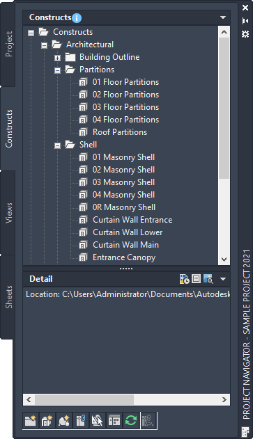
Project Navigator in AutoCAD Architecture 2026 Toolset
Depending on their function within the project, the drawings are classified according to different drawing categories:
Constructs
Constructs contain the geometry representing the building. They are drawing files containing one unique constructed part of the building. Each floor should be represented by at least one construct. If the building is large and complex, each floor can be created from multiple constructs, like one construct for the wall layout, one for the cubicles and furniture, and one for the framing elements.
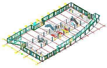
First floor construct
Views
Views are drawings assembled of a number of constructs to represent one specific view of the building. For example, you can create a view drawing for a single floor, containing the constructs for the walls, the furniture, and the framing. Another view drawing could contain the entire building model with all floors in a 3D view. There are also specialized view drawings for details, sections, and elevations.
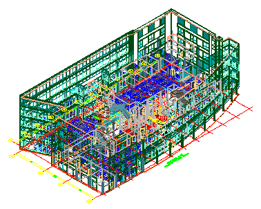
3D view of entire building
Views are also where you add annotation, dimensions, title blocks, and other necessary documentation.
Door and room tags in view drawing
Sheets
Sheets are used to plot and publish the contract documents of your project. Sheet drawings contain xrefed view drawings. You can plot and publish sheets from the project.
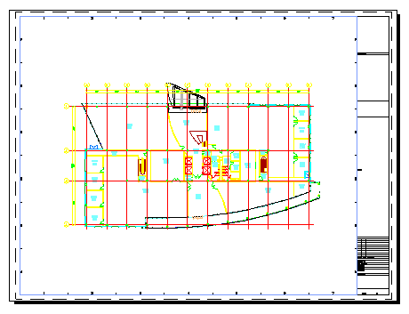
Plotting sheet with building plan view
Elements
Elements are supporting drawings for referencing into constructs. They contain repeatable elements in the building, like for example a bathroom layout that is used on each floor. The bathroom element can be referenced into each floor construct, to save work.
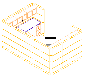
Repeating cubicle element
Project Levels
Levels represent the floors of a building. When creating the project, you define how many levels you need and what height they should have. The drawing files containing the actual model geometry - Constructs - have a location in the project and are assigned to a level in the project.
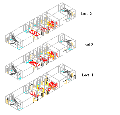
3 different levels in the building model