
Solution tip icons highlight invalid connections between objects. Invalid connections can be fixed by modifying the objects that are causing the invalid connection.
To test for valid connections
- Click
 .
. 
- Expand Multi-Purpose Objects, and then expand Connector Styles.
- Click the Rules tab, and verify the connector style rules.
- Click OK.
Verify the connector style rules:
To show solution tip icons
- Click
MEP View panel
.

The solution tip icons are displayed. You can move your mouse over a solution tip icon to display a tooltip describing the reason for the disconnection.
To change the size of the solution tip icon
- Click
 .
. 
- Enter a size.
The drawing is regenerated and the size of the solution tip icon is updated.
Note: Solution tip icons remain on (visible) until you fix the invalid connection and regenerate your drawing. You can turn off solution tip icons by clicking
MEP View panel
.
To control when solution tip icons display
- Click
 .
. - In the Options dialog box, click the AEC Editor tab.
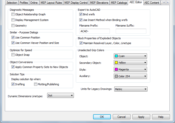
- Under Solution Tip, select options for displaying solution tip icons.
Select Drafting to display solution tip icons as you work in a drawing file. Select Plotting/Publishing to display solution tip icons when plotting or publishing a drawing file.
Note: You can also control the display of solution tip icons while drafting by clicking
MEP View panel
.