
Use this procedure to define any of the following display components of a space in the style:
- Space boundaries (Plan views): You can set the display of the base, net, usable, and gross boundaries. If boundaries are offset from each other, it is a good idea to differentiate them by color, linetype, or lineweight. If you do not need boundary offsets, you could also hide the net, usable, and gross boundaries and their respective hatches, so as not to clutter the drawing.
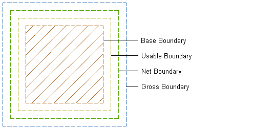
- Boundary hatches (Plan views): Each space boundary has an associated hatch that you can display.

- Above and Below Cut Plane components (Plan views): If the space is cut by an object cut plane, you can define different visuals for the parts that lie above the cut plane and below the cut plane.
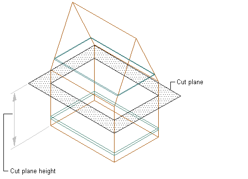
- Calculation cut planes and hatches (Plan views): For 3D freeform spaces, 2 calculation cut planes can be set. This helps to create evaluations of non-uniform space heights. For each of the calculation cut planes, you can set a boundary display and a hatch.
- Floor and ceiling components (Model views): 3D spaces can have floors and ceilings with a user-specified thickness. You can display them in a model view. Note: If the thickness of the ceiling or floor component is set to 0, it does not display in the drawing.
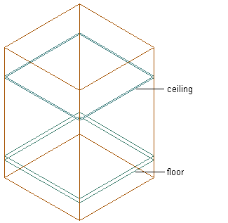
Floor and ceiling components in Model view
- Surfaces and surface components (Model views): 3D freeform spaces are composed of individual surfaces, which can have additional components like door and window openings.
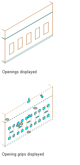
Space surface with surface openings
Note: If a material assignment determines the display properties of components in the space style, you can change the properties of the display component by clearing By Material. You can also override the material assignment with a different material.
- Click
 .
. 
- Expand Architectural Objects, and expand Space Styles.
- Select the space style that you want to change.
- Click the Display Properties tab.
- Select the display representation where you want the changes to appear, and select Style Override.
- Click the Layer/Color/Linetype tab.
- Select the space component to change, and change the following settings:
- Material: If you select By Material, all display settings are taken from the assigned material. Components that cannot be set by material have the check box deactivated.
- Visibility
- Layer
- Color
- Linetype/Lineweight/Linetype Scale
- Plot Style
- Click OK.