
- Open the drawing that contains the style.
- In the Schematic workspace, open the style by doing one of the following:
- Click

 . In the left pane of the Style Manager, select the style.
 - In the drawing, select a schematic line that uses the style, and click .
- Click
- Click the Annotation tab.
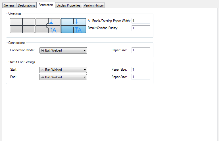
- Under Crossings, select a style for crossing schematic lines.
You can specify that the crossing lines are displayed as is, with an overlap, or with a break.
- If you selected the overlap style or the break style, for Break/Overlap Paper Width, enter the width of the overlap or the break, and for Break/Overlap Priority, enter a number.
- Under Connections, select a connection node symbol for line junctions, and enter a size.
- Under Start & End Settings, select a symbol for the start and end of a line, and enter a size for each.