
10. Add Dimensions to a Design (AutoCAD Foundations)
Dimensions mark the geometric measurements of objects, the distances or angles between objects, or the location of a feature.
There are four types of dimensions:
- Linear: Measures distances using horizontal, vertical, aligned, rotated, baseline (parallel), and continued (chain) dimensions.
- Ordinate: Measures the distance of a point from a specified origin point.
- Radial: Measures the radii and diameters of arcs and circles.
- Angular: Measures the angle formed by two lines or three points.
Parts of a Dimension
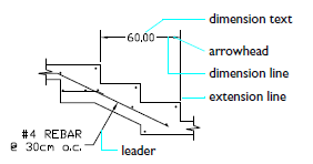
- Dimension text: Reflects dimension value and may include prefixes, suffixes, and tolerances. Alternatively, you can supply your own text or suppress the text entirely.
- Arrowhead: Indicates an end of the dimension line. Several types of arrowheads are available, including architectural ticks and dots.
- Dimension line: Indicates the direction and extent of a dimension. For angles, the dimension line is an arc.
- Extension line: Extends from what's being dimensioned to the dimension line.
- Leader: Forms a solid line leading from an annotation to the referenced feature. Depending on the dimension style, leaders can be created automatically when dimension text won’t fit between extension lines. You can also create leader lines to connect text or a block with a feature.
Dimensions are associative. This means that measurements update automatically as you modify objects.
The following video demonstrates some of the learning objectives covered in this topic:
Learning Objectives
Prerequisites
You should know how to do the following before continuing:
Prepare for the Exercises
To follow along with the exercises in this topic, download the ZIP file containing the sample drawings.
![]() Download: Sample drawing files used for the following exercises
Download: Sample drawing files used for the following exercises
The ZIP file contains all drawings used for the exercises and only needs to be downloaded once. Keep the ZIP file to restore the original state of the sample drawings.
Set a Dimension Style as Current
Dimension styles establish and enforce drafting standards. By setting up your dimension style, you can specify virtually every aspect of a dimension's appearance and behavior.
The default dimension style is named either Standard (imperial) or ISO-25 (metric). It is assigned to all dimensions until you set another style as the current dimension style.
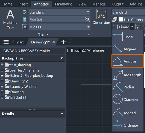
To access settings and tools related to dimensions, click the Annotate tab > Dimensions panel.
Try It: Select Your Dimension Style
In this exercise, choose your dimension style and set it current.
Open Bracket.dwg, linked above.
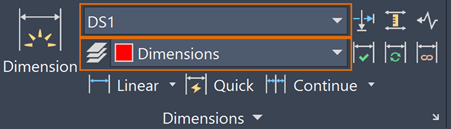
Click the Annotation tab > Dimension Style and set the DS1 dimension style current.
Set Dimensions as the current layer.
Add Linear Dimensions
Horizontal, vertical, rotated, and aligned dimensions are useful for measuring distances between two points. Based on your design, you might dimension the length of a wall, the distance between the center of two holes, or the height of a feature shown in a section or elevation view.
You can create a linear dimension by:
Selecting a linear object or straight segment of an object, and then moving the cursor away from the selected object to place the dimension line.
Specifying two points and then moving the cursor away from the points to place the dimension line.
If points 1 and 2 are not on the same horizontal line, press Shift to force the dimension line to be horizontal.
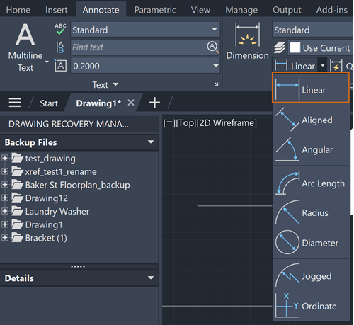
To create these dimensions, click Annotate tab > Dimensions panel > Dimension Types drop-down menu:
Linear: Creates a linear dimension with a horizontal, vertical, or rotated dimension line.
Aligned: Creates a linear dimension that is aligned with the origin points of the extension lines.
Try It: Add a Linear Dimension
In this exercise, try out creating linear and aligned dimensions.
Open Bracket.dwg.
Click Annotate tab > Dimensions panel > Linear.
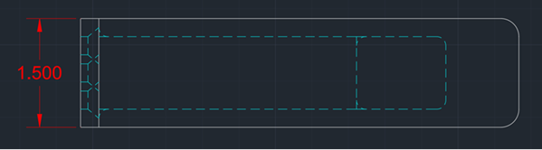
When you see the Command prompt appear, press Enter to choose the Select object option.

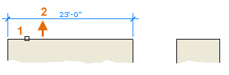
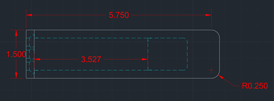
Select the top leftmost line, then drag to the left to draw the linear dimension. Your drawing should look like this:
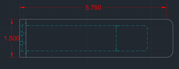
To create a linear dimension using two points, click Linear and then the two endpoints of the line you want to dimension. Do this with the top horizontal line. Your drawing should look like this:
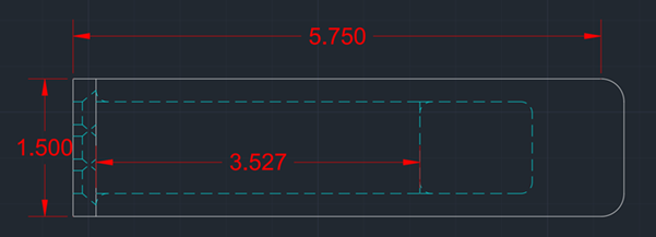
To create an aligned dimension, click Aligned. Press Enter to choose the Select object option, then dimension one of the dotted blue lines. Your drawing should look this:
Add Angular Dimensions
Angular dimensions are used to communicate the angle of two lines or between three points. Based on your designs, you might use an angular dimension to indicate the angle of non-orthogonal walls in a floor plan or angles between gear teeth in a mechanical part.
Try It: Add Angular Dimensions
In this exercise, choose two sides of an angle to dimension.
Open Bracket.dwg.
Click Annotate tab > Dimensions panel > Angular.
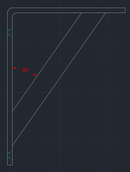
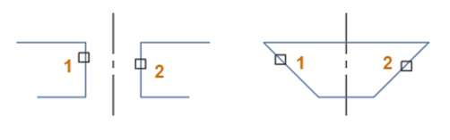
In the bottom left bracket, choose two sides of an angle and drag outwards to create an angular dimension.
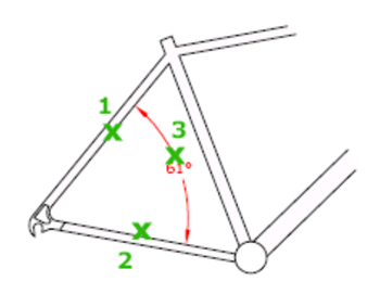
Your drawing will look something like this:
Try this with the other angles in the drawing.
Add Radial Dimensions
Radial dimensions are used to communicate the radius and diameter of arcs and circles, respectively. Based on your designs, you might use a radius dimension to dimension a fillet on a window detail or square tube. Diameter dimensions can be used for a hole size on a mechanical part or inner dimension of a pipe.
Try It: Add Radial Dimensions
In this exercise, measure radius and diameter with dimensions.
Open Bracket.dwg.
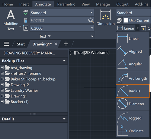
Click Annotate tab > Dimensions panel > Radius.
To measure radius, click an arc, such as the rounded corners in the top bracket. Your drawing will look like this:
To measure diameter, click Annotate tab > Dimensions panel > Diameter.
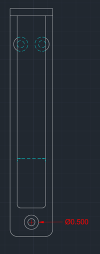
Click a circle in the drawing. Your drawing will look something like this:
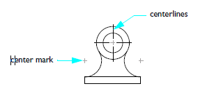
Add Center Marks
Center marks identify the exact center of circles and arcs. You might use center marks to indicate the center of holes and shafts in a mechanical design or mark the center of columns and pipes in an architectural drawing for accurate placement of these elements on site.
Try It: Add Center Marks
In this exercise, create center marks in circles.
Open Bracket.dwg.
Click Annotate tab > Centerlines panel > Center Mark.
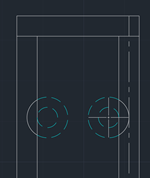
In the bottom right bracket, click on the circle on the right. Your drawing should look something like this:
Add Centerlines
Centerlines are often used to indicate the axis of symmetry for objects, such as symmetrical parts in mechanical designs or architectural features. They're useful in aligning structural elements such as beams, columns, or pipes, which ultimately contributes to the accurate construction and assembly of these elements on-site.
Try It: Add Centerlines
In this exercise, add lines to the center of your circles.
Open Bracket.dwg.
To draw a centerline, click Annotate tab > Centerlines panel > Centerline.
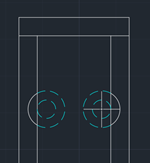
Click the two parallel lines to the right of the center mark we drew in the previous section. Your drawing should now look something like this:
Add Baseline and Continued Dimensions
Baseline dimensions measure distances from a single, consistent reference point (the baseline) to multiple features. This ensures that all measurements are taken from a common starting point, reducing cumulative errors that can occur with chain dimensions.
Continued dimensions keep dimensioning from the point you stopped dimensioning, which allows efficiency when dimensioning multiple times.
Try It: Add Baseline and Continued Dimensions
In this exercise, draw baseline and continued dimensions.
Open Bracket.dwg. Make sure your drawing has no dimensions on it from previous activities.
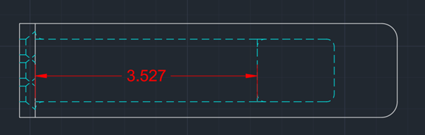
In the topmost bracket, draw a linear dimension for the bottom left dotted blue line. Your drawing will look something like this:
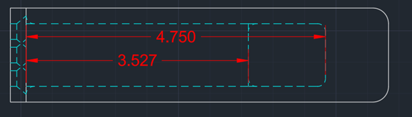
To draw a baseline dimension, click Annotate tab > Dimensions panel > Continue/Baseline drop-down menu > Baseline.
Select the origin point of the dimension line in the previous image.
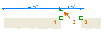
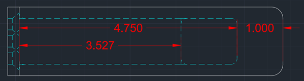
Then drag out the dimension line to the end of the blue dotted line. Your drawing will look like this:
To draw a continued dimension, click Annotate tab > Dimensions panel > Continue/Baseline drop-down menu > Continue.
Select the end point of the longer dimension line from the previous image.
Drag the dimension line to the end of the white bracket. Your drawing will look like this:
Press Esc to exit dimensioning.
Move Dimensions
After you place a dimension, you might want to align it with another dimension or move the dimension text to make it easier to read. Use grips to move dimension lines and text.
To display the grips, select the dimension. Hover over a grip to see this context menu.
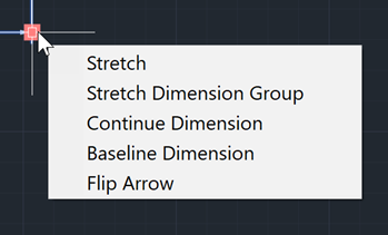
Then, choose Stretch or click the grip at the end of the dimension line to drag the dimension line. To relocate the dimension text, click the grip on the dimension text and drag.
Summary
We've now learned how to set dimension styles current, move dimension lines and text, and add dimensions that measure circles, angles, and lines. Dimension lines and text are powerful tools in our AutoCAD toolkit that make our drawings both precise and reliable as guidelines for construction and assembly.
Related Commands
| Command | Description |
|---|---|
| CENTERLINE | Creates centerline geometry associated with selected lines and linear polyline segments. |
| CENTERMARK | Creates an associative, cross-shaped mark at the center of a selected circle or arc. |
| DIM | Creates multiple dimensions and types of dimensions with a single command. |
| DIMALIGNED | Creates an aligned linear dimension. |
| DIMANGULAR | Creates an angular dimension. |
| DIMBASELINE | Creates a linear, angular, or ordinate dimension from the baseline of the previous or selected dimension. |
| DIMCONTINUE | Creates a dimension that starts from an extension line of the previous or selected dimension. |
| DIMDIAMETER | Creates a diameter dimension for a circle or an arc. |
| DIMEDIT | Edits dimension text and extension lines. Find Rotates, modifies, or restores dimension text. |
| DIMLINEAR | Creates a linear dimension. |
| DIMRADIUS | Creates a radius dimension for a circle or an arc. |
| DIMROTATED | Creates a rotated linear dimension. |
| DIMSTYLE | Creates and modifies dimension styles. |
| DIMTEDIT | Moves and rotates dimension text and relocates the dimension line. |