
2A. Architectural Design: House Deck (AutoCAD Foundations)
In this exercise, you will create a plan view of a deck that is being proposed.
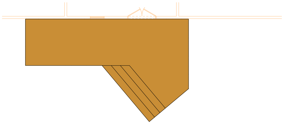
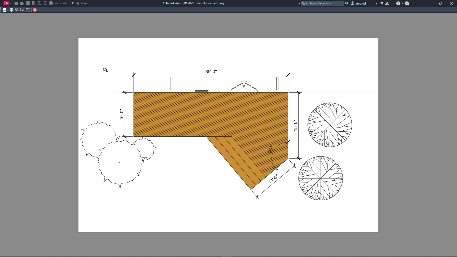
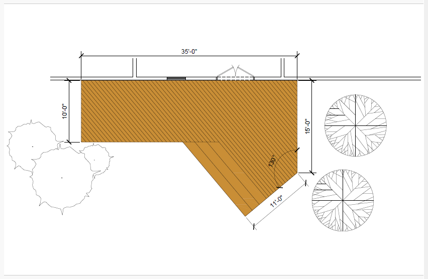
After you complete all the exercises, you should have a drawing that looks similar to the following image.
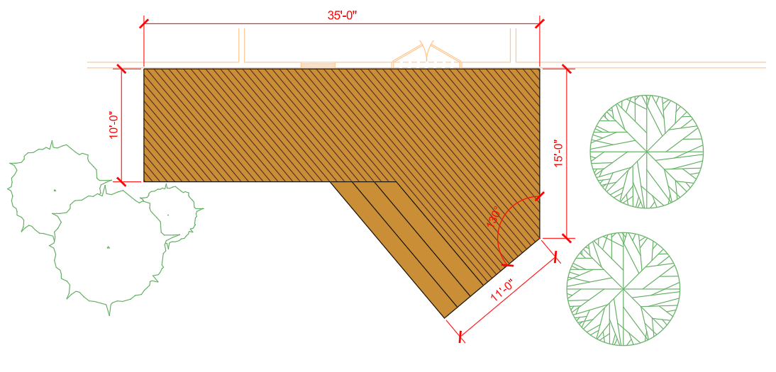
The completed drawing can be found in the House - Deck - Complete.dwg file.
Learning Objectives
- Open and create a drawing
- Create and modify 2D objects
- Create and use layers
- Apply hatches and fills
- Add annotation
- Add center marks and dimensions
- Insert blocks
- Plot a drawing to a PDF file
Prerequisites
AutoCAD 2024 or later has been installed
Don't currently have AutoCAD installed? You can download AutoCAD from your Autodesk Account or a trial from Autodesk.com.
Prepare for the Exercises
To follow along with the exercises in this topic, download the ZIP file containing the sample drawings.
![]() Download: Sample drawing files used for the following exercises
Download: Sample drawing files used for the following exercises
The ZIP file contains all drawings used for the exercises and only needs to be downloaded once. Keep the ZIP file to restore the original state of the sample drawings.
Before Starting
Here are a few things you should know before getting started:
- Values to be entered or typed in response to a command or dialog box value are presented in bold.
- Pressing the Esc key ends the current command. Once the current command is ended, you can start the command over or undo a recent change.
- Clicking Undo on the Quick Access toolbar reverses the effect of recently used commands.Find
Exercise 1: Open the sample drawing
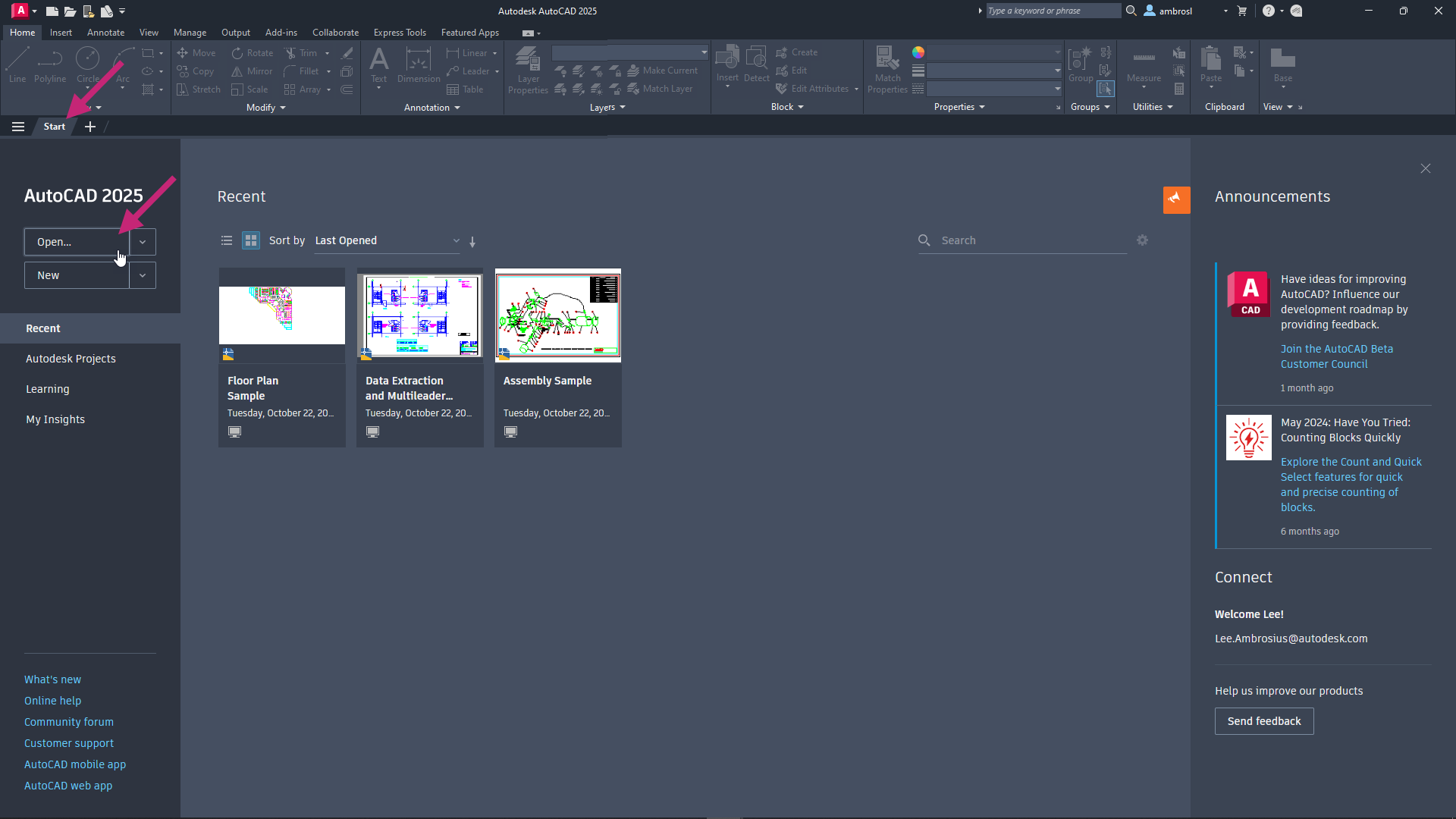
Open a sample drawing file that will be used for the remainder of the exercises.On the Start tab, click Open.
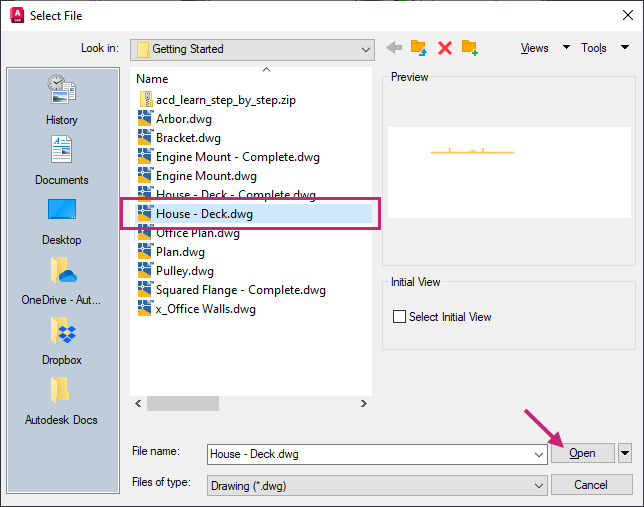
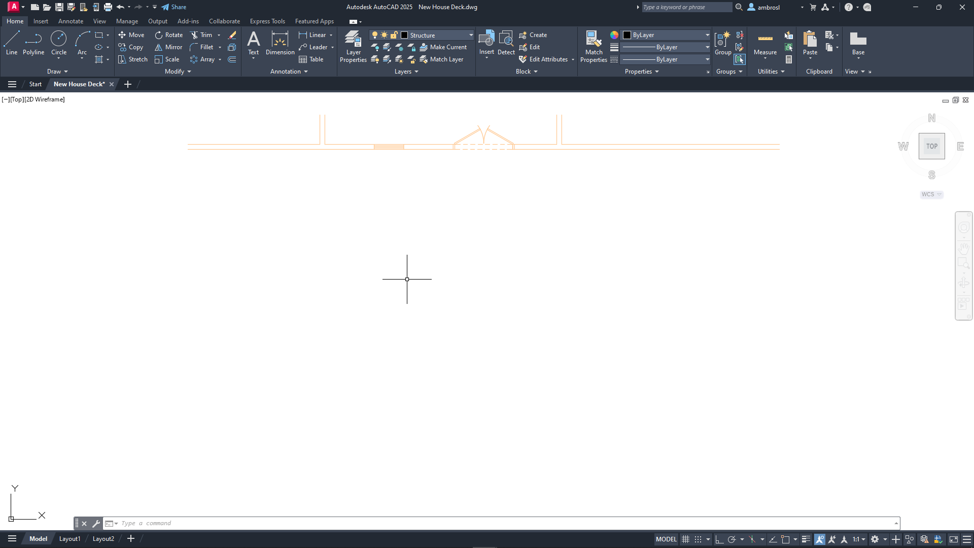
In the Select File dialog box, browse to the sample files you previously downloaded and select the House - Deck.dwg file. Click Open.
The drawing should look like the following image. This drawing contains part of an exterior wall of a house with a French style patio door and window.

Exercise 2: Save the drawing with a new name
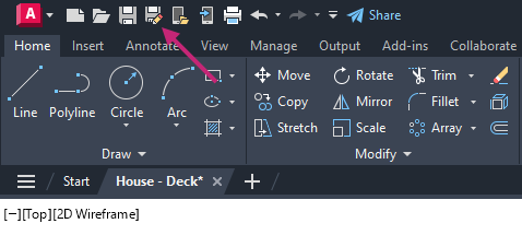
Save the sample drawing with a new name and allow changes to be saved as you progress through the exercises.- On the Quick Access toolbar, click Save As.Find
In the Save Drawing As dialog box, browse to the Documents folder.
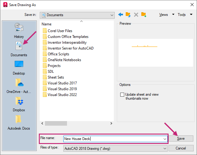
In the File Name text box, select the current name and type New House Deck. Click Save.
A new drawing file is created and named New House Deck in the Documents folder. Make sure you continue with this file for the remainder of the exercises.
Exercise 3: Navigate the drawing
Use the Zoom and Pan tools on the Navigation Bar, which you'll continue to use in the following exercises.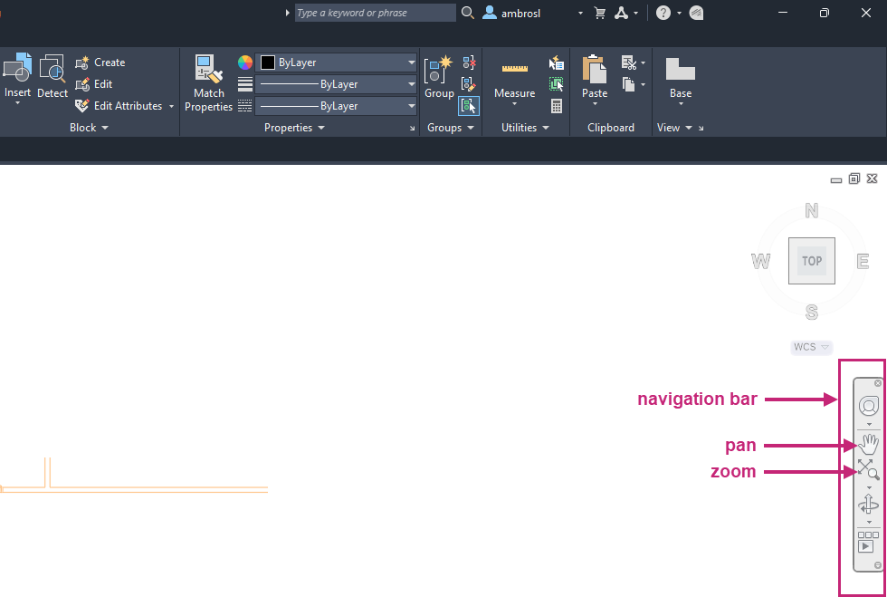
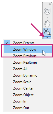
- On the Navigation Bar, click Zoom drop-down menu > Zoom Window.Find
At the Specify first corner: prompt, in the drawing area, click a point near (1) in the following image.
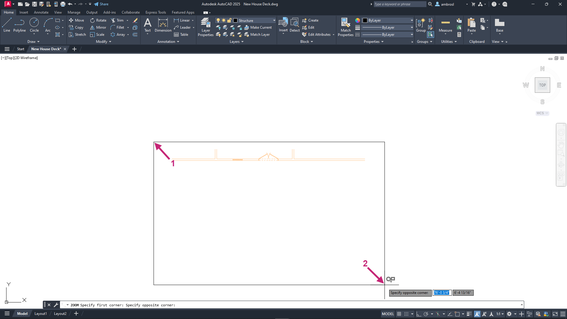
At the Specify opposite corner: prompt, in the drawing area, click a point near (2) in the previous image.
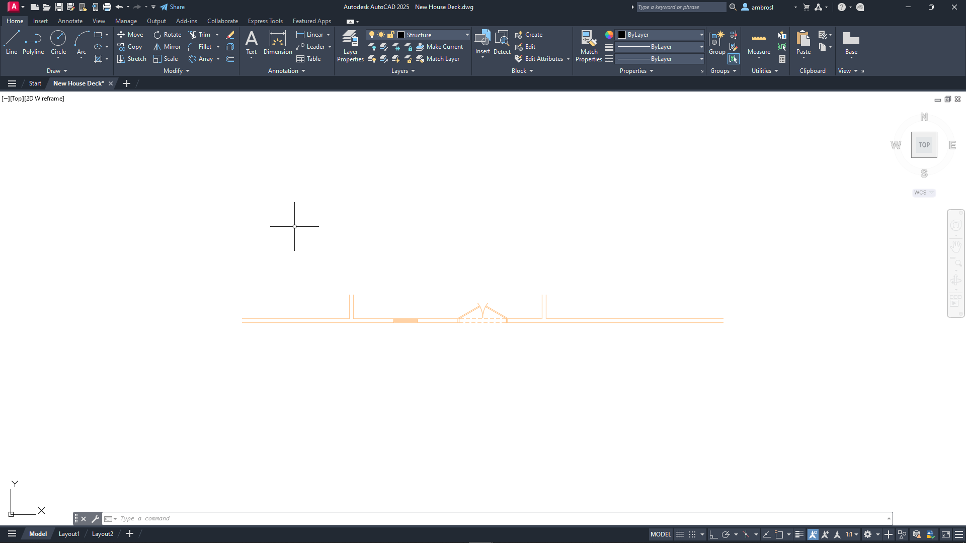
The objects within the window are enlarged and centered in the drawing area.
- On the Navigation Bar, click Zoom drop-down menu > Zoom Extents.Find
The extents of all objects should now fill the entire drawing window.

- On the Navigation Bar, click Zoom drop-down menu > Zoom Out.Find
The objects should now appear smaller and provide some additional space to work.
- On the Navigation Bar, click Pan.Find
In the drawing area, click and drag upward, and then release once the wall is near the top of the drawing area.
The exterior wall should now be near the top of the drawing window.
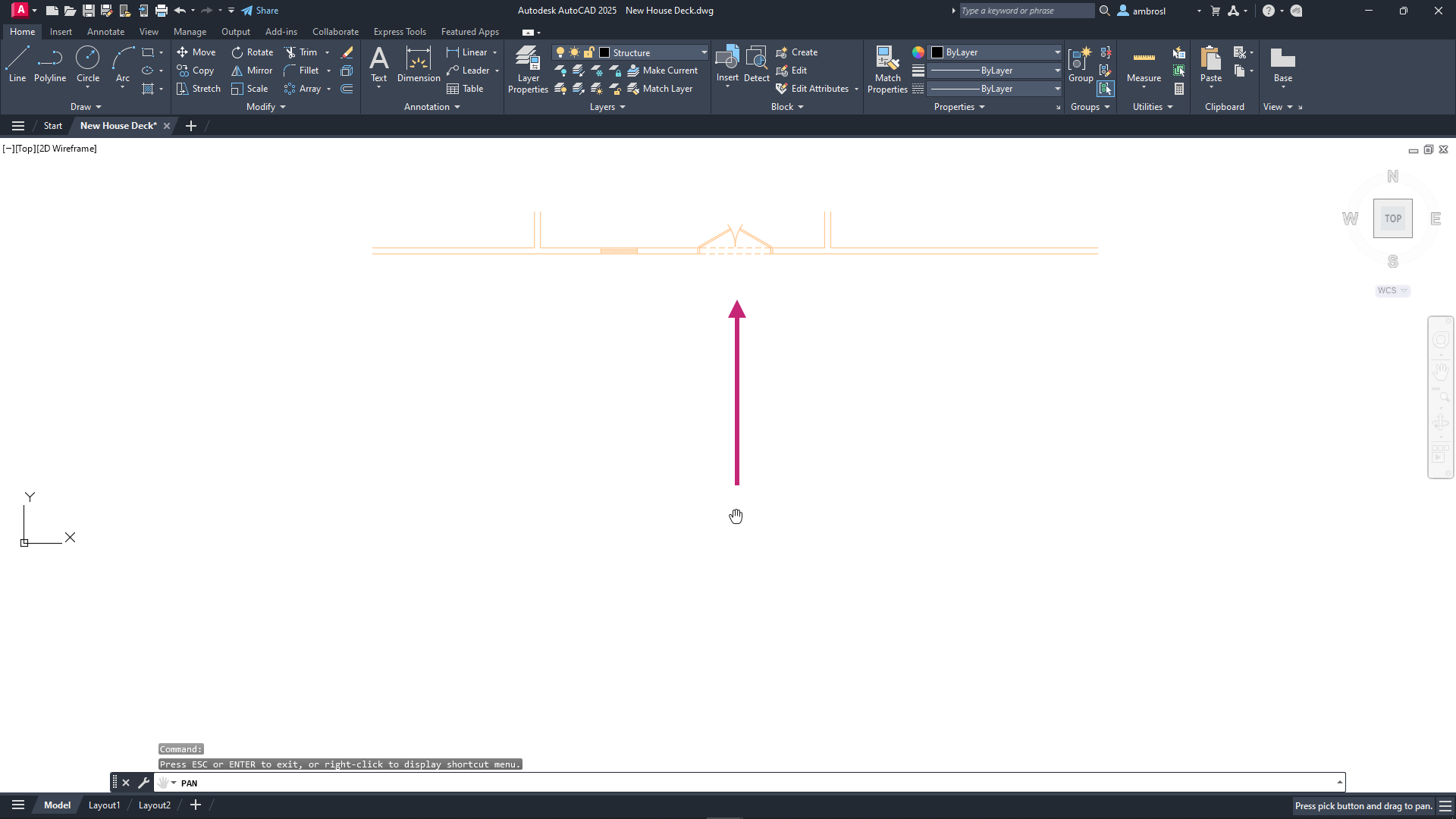
Press the Esc key to exit the PAN command.
- On the Quick Access toolbar, click Save.Find
When using a mouse you can hold down the mouse wheel to pan the drawing, double-click the mouse wheel to zoom to the extents of the drawing, and scroll the mouse wheel to zoom in and out. If you're using a touchpad, you can drag two fingers to zoom in and out.
Exercise 4: Create lines to define the deck shape
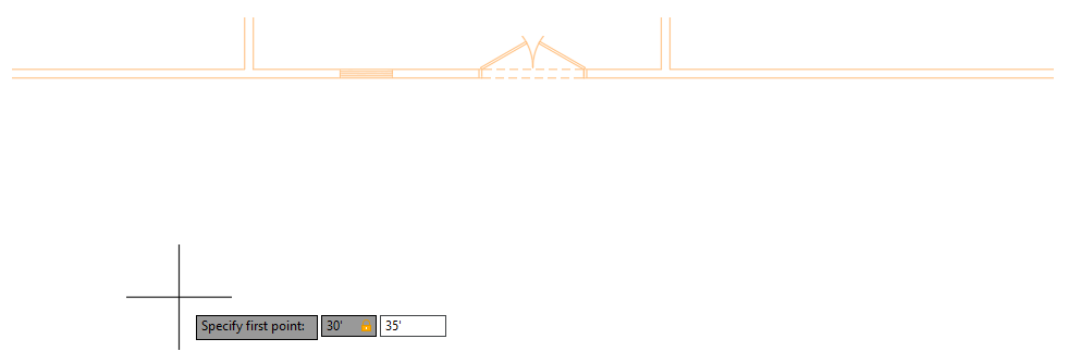
Create straight- and angled-line segments that will create the outline of the deck.- On the ribbon, click Home tab > Draw panel > Line.Find
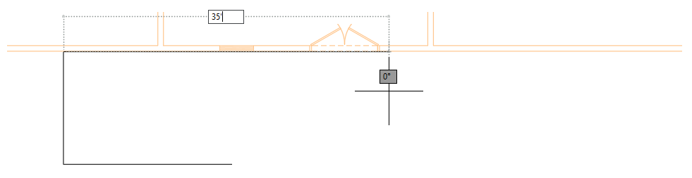
At the Specify first point: prompt, type 30',35' and press Enter to accept the entered value.
Going forward, whenever you see "enter" followed by a value in bold, the bold text should be typed followed by the pressing of the Enter key.
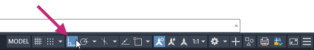
- On the status bar, click the Restrict Cursor Orthogonally button to turn the drafting setting on.Find
The button should now be highlighted and blue in color.
With this setting enabled, the next point you specify will be drawn 0 or 90 degrees from the previous point.
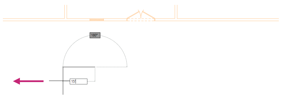
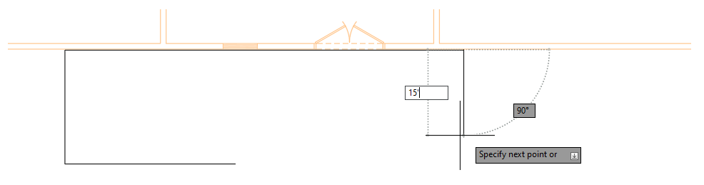
At the Specify next point or [Undo]: prompt, drag the cursor to the left and enter 15'.
You should now have a single line segment in the drawing with a length of 15'-0".
At the Specify next point or [Undo]: prompt, press Enter to end the LINE command.
Pressing Enter ends the LINE command resulting in no command being active which can be seen by the standard Command: prompt in the Command Line window.

At the Command: prompt, press Enter to repeat the most recently used command which was the LINE command.
The LINE command should start and prompt you for the first point.
At the Specify first point: prompt, press Enter to continue from the end point of the previously drawn line.
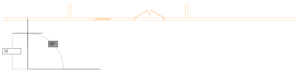
At the Specify next point or [Undo]: prompt, drag the cursor upward and enter 10'.
At the Specify next point or [Close/Undo]: prompt, drag the cursor to the right and enter 35'.
At the Specify next point or [Close/Undo]: prompt, drag the cursor downward and enter 15'.
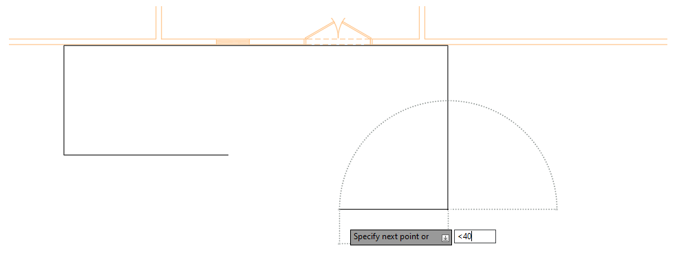
At the Specify next point or [Close/Undo]: prompt, enter <40 and drag the cursor.
You should notice the cursor is restricted now at an angle of 40 and 220 degrees, and not 0 and 90.
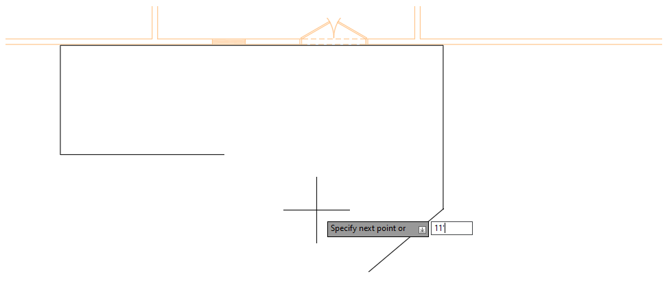
At the Specify next point or [Close/Undo]: prompt, drag the cursor downward and enter 11'.
At the Specify next point or [Close/Undo]: prompt, enter <130, drag the cursor upward and then enter 18'.
You should notice the cursor was restricted to an angle of 130 and 310 degrees.
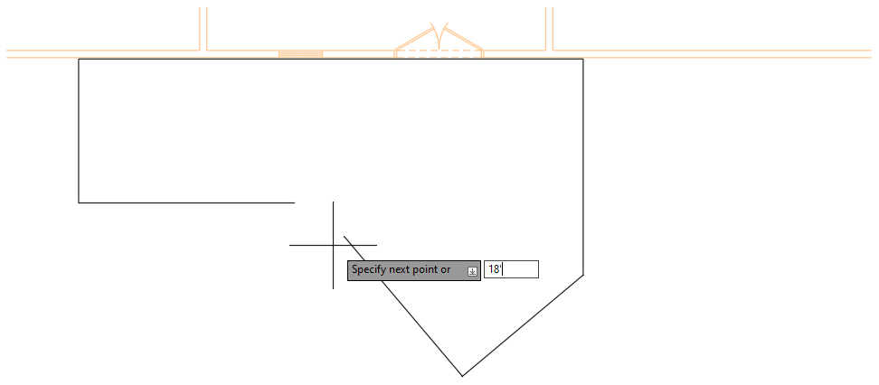
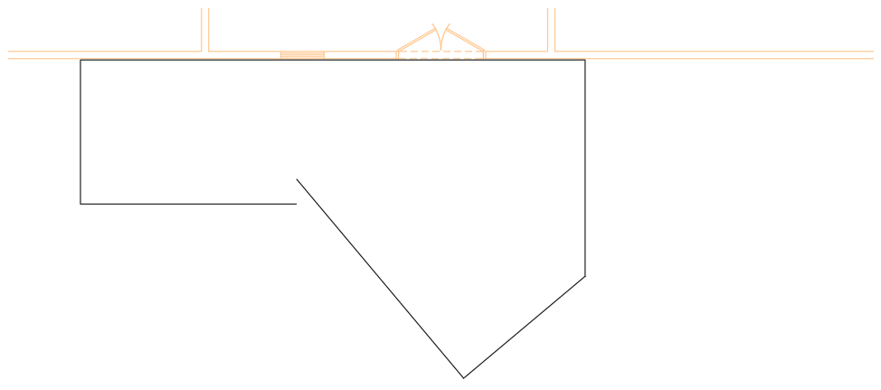
At the Specify next point or [Close/Undo]: prompt, press Enter to end the LINE command.
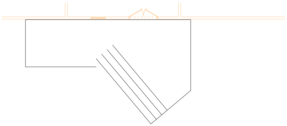
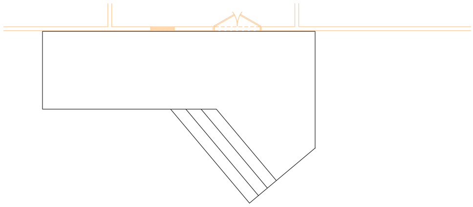
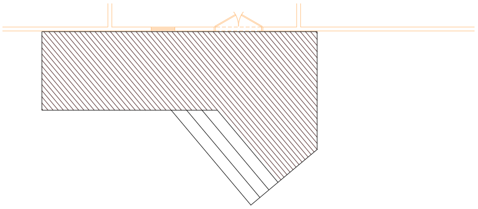
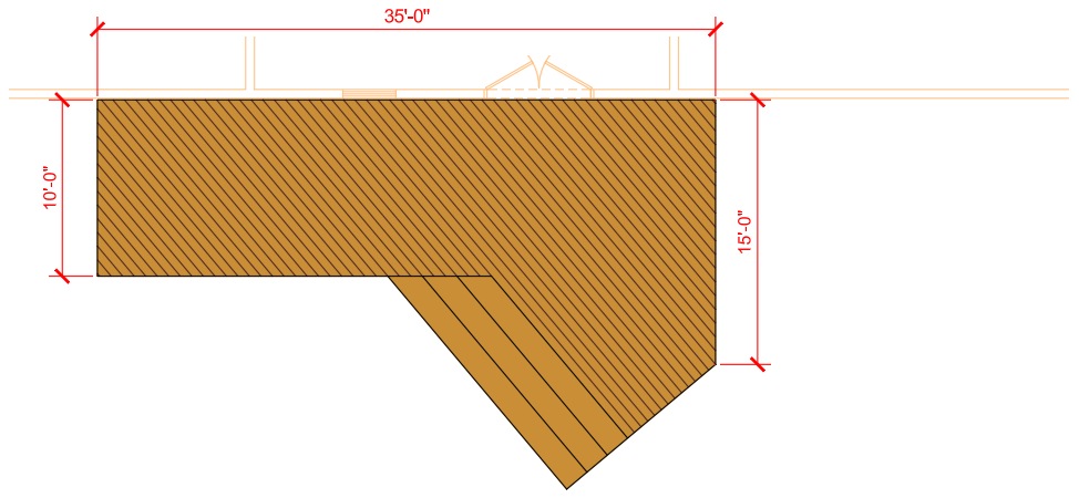
The design should look similar to the following image.
- On the Quick Access toolbar, click Save.Find
Exercise 5: Offset, extend, and trim lines
Offset, extend, and trim objects to create the stairs of the deck.- On the ribbon, click Home tab > Modify panel > Offset.Find
At the Specify offset distance or [Through/Erase/Layer] <Through>: prompt, enter 18.
When a foot or inch mark is not used, the value is interpreted as inches in this drawing because the drawing units are set to Architectural.
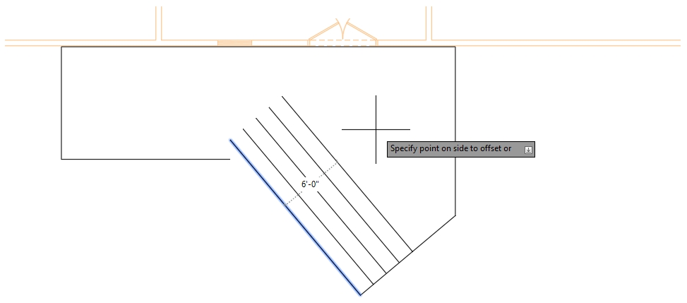
At the Select object to offset or [Exit/Undo] <Exit>: prompt, select the angled line indicated in the following image.
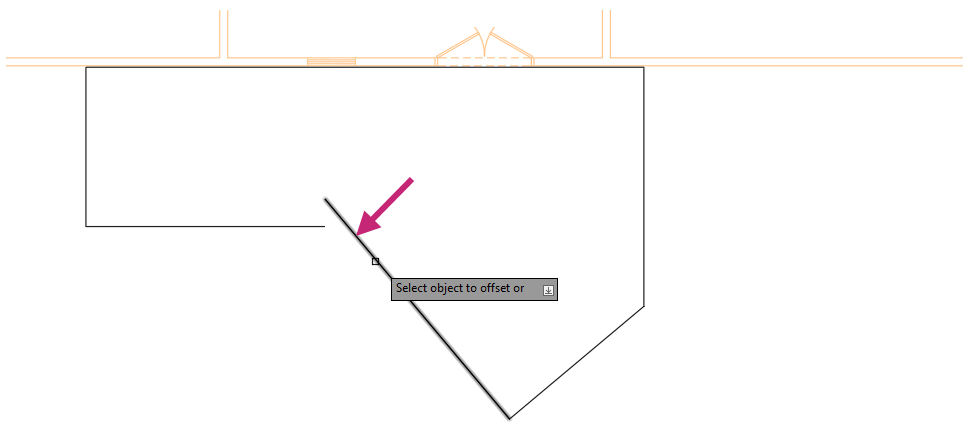
At the Specify point on side to offset or [Exit/Multiple/Undo] <Exit>: prompt, enter m.
At the Specify point on side to offset or [Exit/Undo] <next object>: prompt, move the cursor to the right of the angled line and near the vertical line on the right.
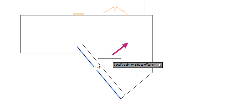
Click three times to offset the selected line.
Press Esc to exit the OFFSET command.
- Click Home tab > Modify panel > Trim/Extend drop-down menu > Extend.Find
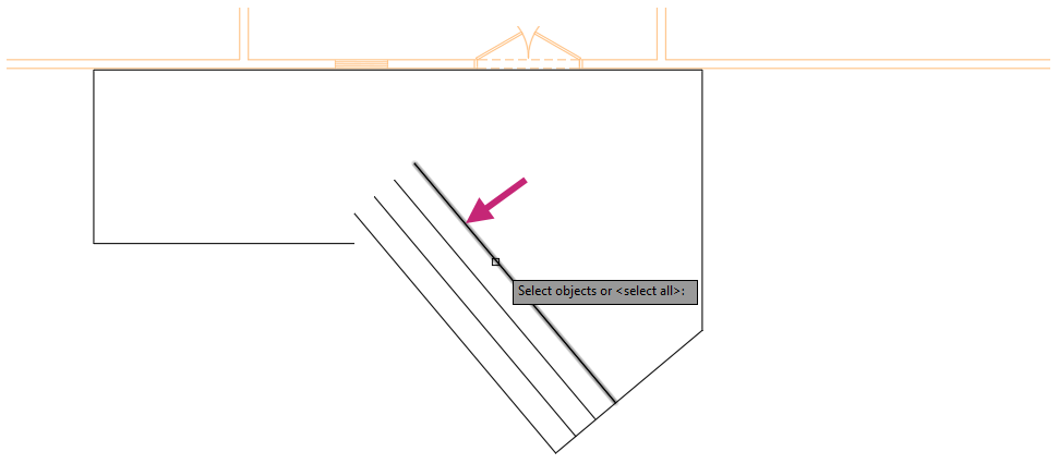
At the Select object to extend or shift-select to trim or [Boundary edges/Crossing/mOde/Project]: prompt, enter b.
At the Select objects or <select all>: prompt, select the right-most angled line you created by offsetting as shown in the following image and press Enter to end object selection.
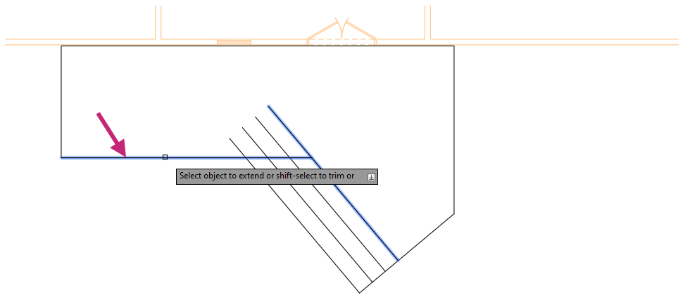
At the Select object to extend or shift-select to trim or [Boundary edges/Crossing/mOde/Project]: prompt, select the horizontal line as shown in the following image and press Enter to end object selection.
- Click Home tab > Modify panel > Trim/Extend drop-down menu > Trim.Find
At the Select object to trim or shift-select to extend or [cuTting edges/Crossing/mOde/Project/eRase]: prompt, in the drawing area, click a point near (1) in the following image.
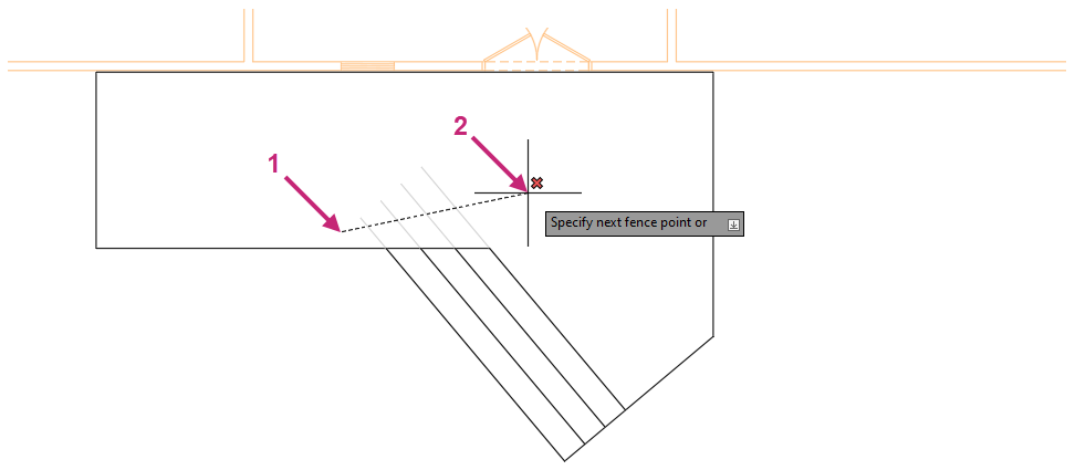
At the Specify next fence point or [Undo]: prompt, in the drawing area, click a point near (2) in the previous image.
At the Select object to trim or shift-select to extend or [cuTting edges/Crossing/mOde/Project/eRase]: prompt, press Enter to end the command.
- On the Quick Access toolbar, click Save.Find
Exercise 6: Apply hatches and fills
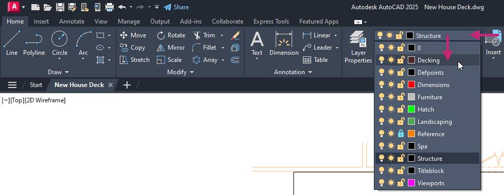
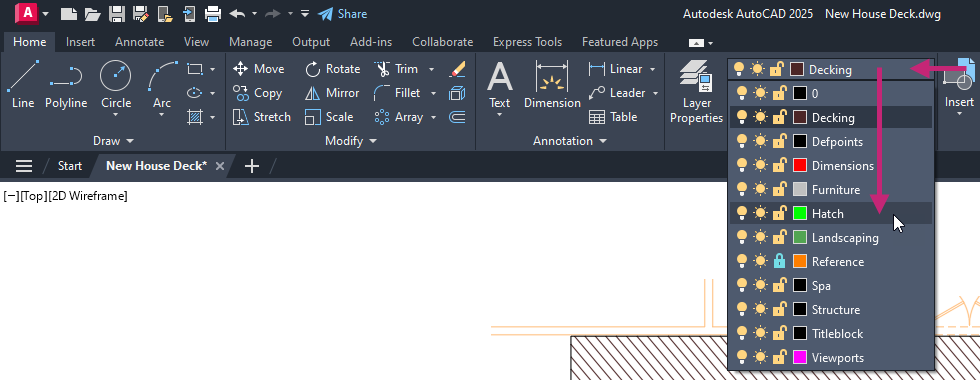
Apply hatch patterns and fills to enhance the visualization of the deck.- On the ribbon, click Home tab > Layers panel > Layers drop-down list and choose Decking.Find
- Click Home tab > Draw panel > Hatch drop-down menu > Hatch.Find
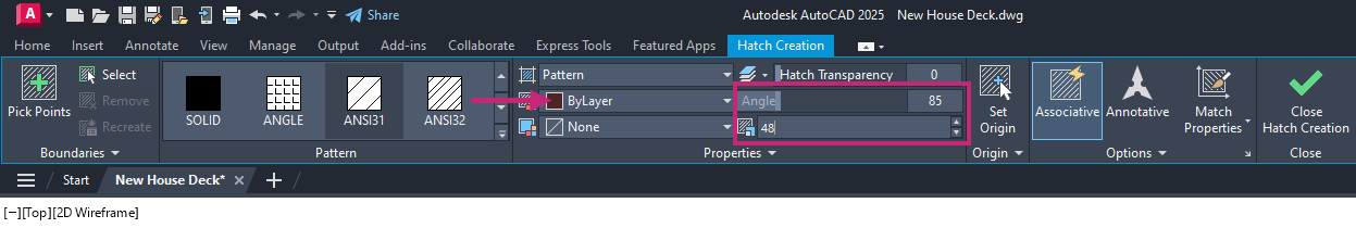
Click Hatch Creation contextual tab > Pattern panel > Pattern gallery > ANSI31.
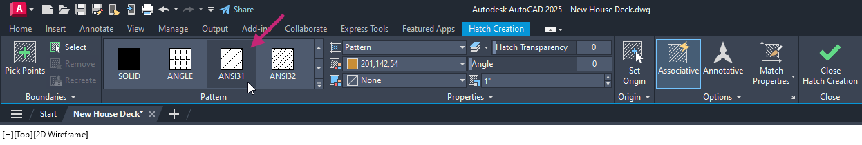
On the Hatch Creation contextual tab > Properties panel, do the following:
Click in the Color drop-down list and choose ByLayer.
Click in the Angle text box and enter 85.
Click in the Scale text box and enter 48.
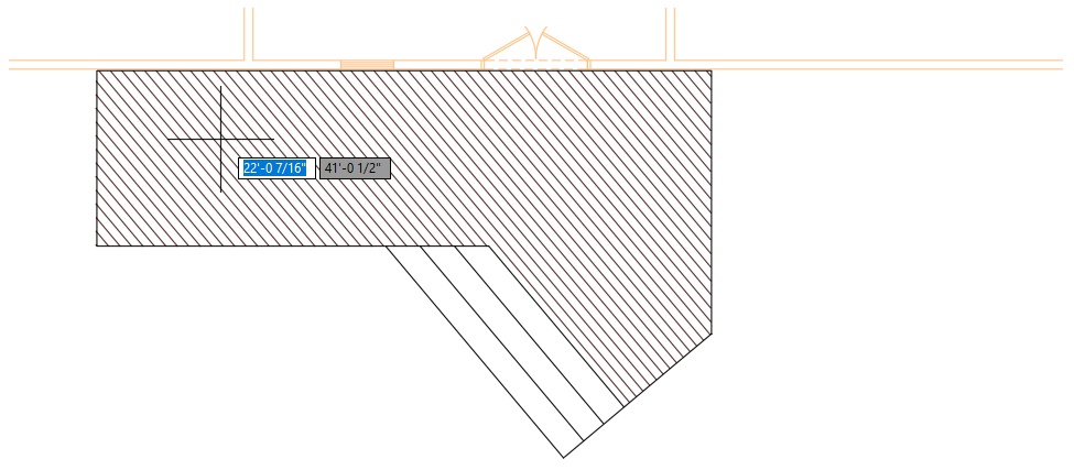
At the Pick internal point or [Select objects/Undo/seTtings]: prompt, click inside of the large area of the deck.
The hatch pattern is applied to the closed area and looks like planks for the decking.
- On the Hatch Creation contextual tab > Origin panel > Set Origin.Find
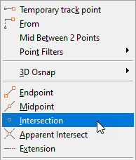
At the Specify origin point: prompt, hold down the Shift key and right-click.
- From the Object Snap menu, choose Intersection.
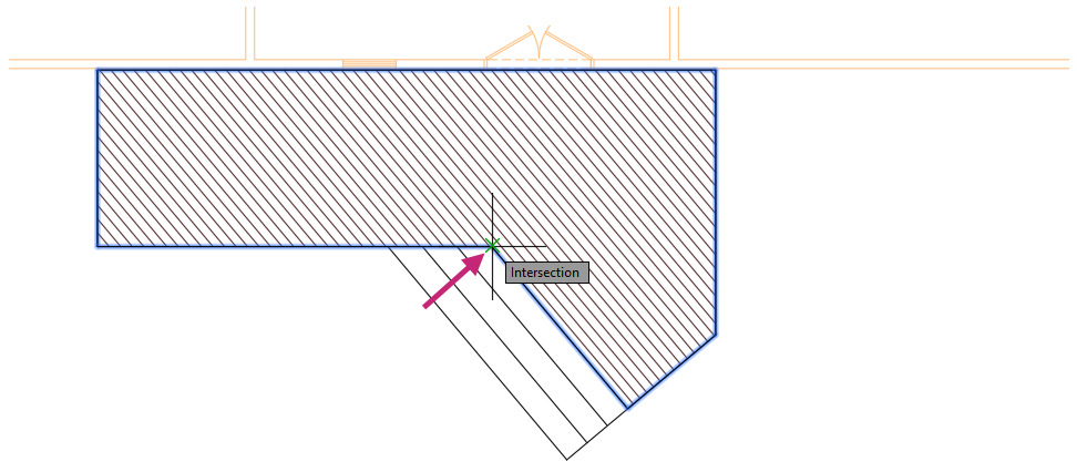
At the Specify origin point:_int of prompt, specify the intersection of the two lines shown in the following image.
The hatch pattern shifts to the right and aligns to the new origin.
At the Pick internal point or [Select objects/Draw/Undo/seTtings]: prompt, press Enter to end the command.
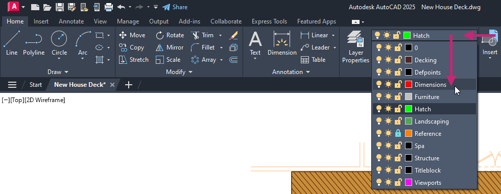
- Click Home tab > Layers panel > Layers drop-down list and choose Hatch.Find
- Click Home tab > Draw panel > Hatch drop-down menu > Hatch.Find
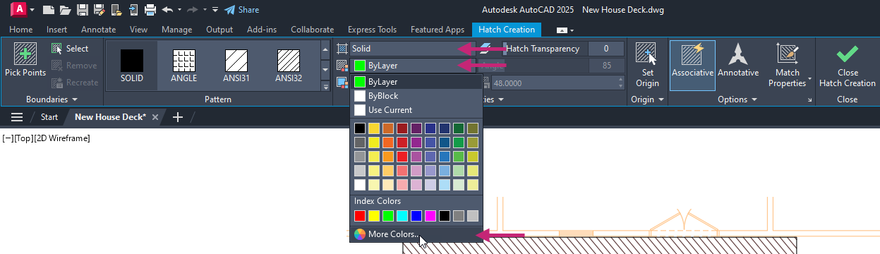
On the Hatch Creation contextual tab > Properties panel, do the following:
Click in the Hatch Type drop-down list and choose Solid.
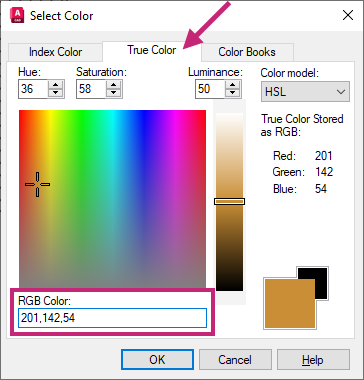
Click in the Color drop-down list and choose More Colors.
In the Select Color dialog box, True Color tab, click in the RBG/Color text box and replace the value with 201,142,54. Click OK.
At the Pick internal point or [Select objects/Undo/seTtings]: prompt, click inside of the four areas that make up the stairs and main part of the deck, and then press Enter to end the command.
The hatch applied is the color you specified and is not inherited from the layer on which it was created. You might also notice the previous hatch is covered by the new solid hatch, let's fix that next.
Before continuing, you will want to make sure Selection Cycling is disabled to simplify object selection.
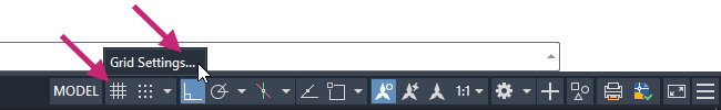
- On the status bar, right-click the Grid Drawing Display button and choose Grid Settings.Find
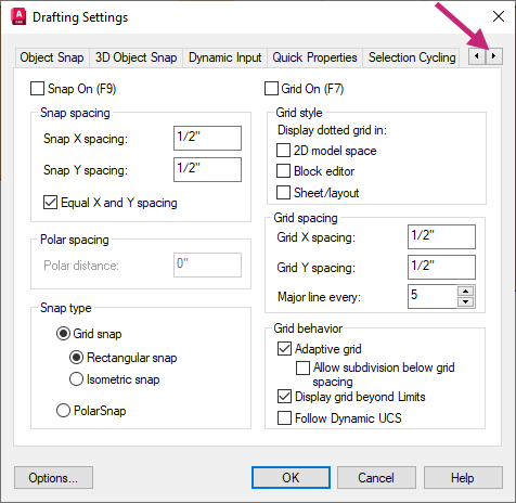
In the Drafting Settings dialog box, click the right arrow adjacent to the tabs until you see the Selection Cycling tab.
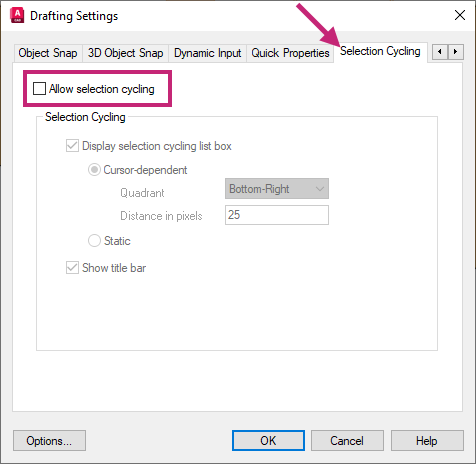
Click the Selection Cycling tab and clear the Allow Selection Cycling check box. Click OK.
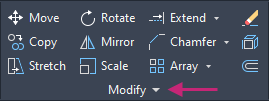
- On the ribbon, click Home tab > Modify panel (expanded) > Draw Order drop-down menu > Send to Back.Find
At the Select objects: prompt, move the cursor over the solid hatch object applied to one of the steps.
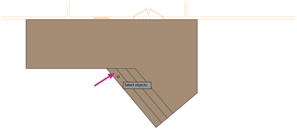
With the solid hatch object highlighted, click to select the hatch and press Enter to end object selection.
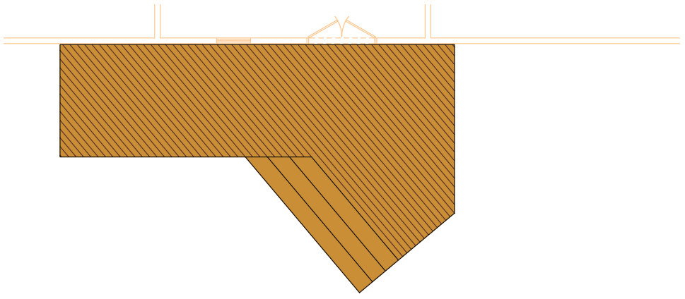
The solid hatch object is moved behind the hatch object with the angled lines (ANSI31) pattern.
- On the Quick Access toolbar, click Save.Find
Exercise 7: Add basic overall dimensions
Add dimensions to communicate the overall dimensions of the deck.Before continuing, you will want to make sure Selection Cycling is disabled to simplify object selection.
- On the status bar, right-click the Grid Drawing Display button and choose Grid Settings.Find
In the Drafting Settings dialog box, click the right arrow adjacent to the tabs until you see the Selection Cycling tab.
Click the Selection Cycling tab and clear the Allow Selection Cycling check box. Click OK.
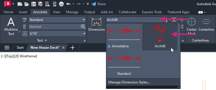
On the ribbon, click Home tab > Layers panel > Layers drop-down list and choose Dimensions.
Click Annotate tab > Dimensions panel > Dimension Styles drop-down list and choose Arch48.
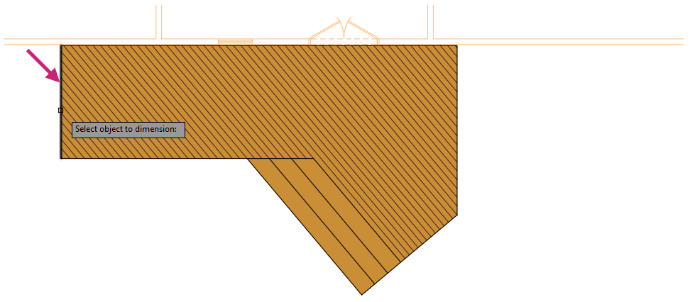
- Click Annotate tab > Dimensions panel > Dimensions drop-down menu > Linear.Find
At the Specify first extension line origin or <select object>: prompt, press Enter to select the object to dimension.
At the Select object to dimension: prompt, select the left-most vertical line of the deck.
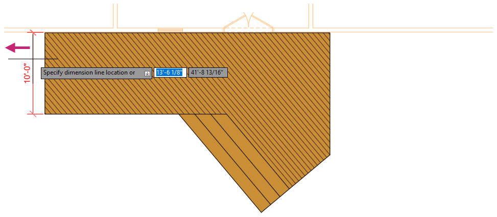
At the Specify dimension line location or [Mtext/Text/Angle/Horizontal/Vertical/Rotated]: prompt, specify a point to the left of the vertical line.
Repeat steps 3-6 and dimension the top-most horizontal line of the deck.
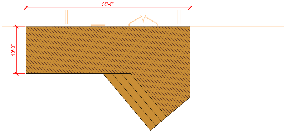
Repeat steps 3-6 and dimension the right-most vertical line of the deck.
- Click Annotate tab > Dimensions panel > Dimensions drop-down menu > Aligned.Find
At the Specify first extension line origin or <select object>: prompt, press Enter to select the object to dimension.
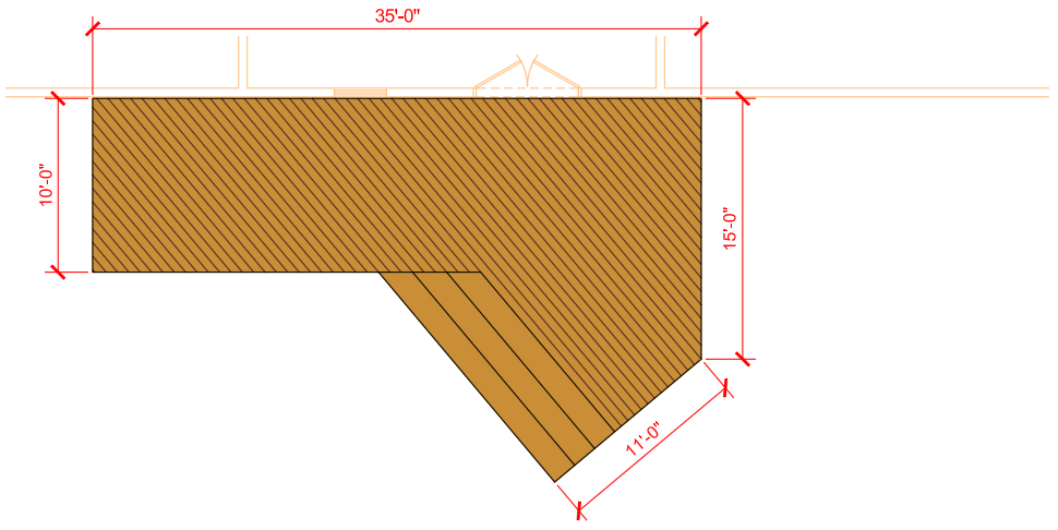
At the Select object to dimension: prompt, select the outer-most angled line of the stairs.
At the Specify dimension line location or [Mtext/Text/Angle]: prompt, specify a point below the angled line.
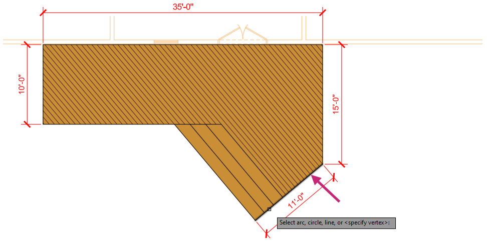
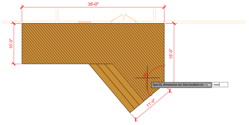
- Click Annotate tab > Dimensions panel > Dimensions drop-down menu > Angular.Find
At the Select arc, circle, line, or <specify vertex>: prompt, select the outer-most angled line of the stairs.
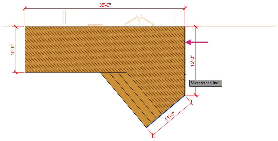
At the Select second line: prompt, select the right-most vertical line of the deck.
At the Specify dimension arc line location or [Mtext/Text/Angle/Quadrant]: prompt, enter non and specify a point inside of the deck.
- On the Quick Access toolbar, click Save.Find
Exercise 8: Insert landscaping blocks
Insert blocks to help communicate the deck design in the planned space.On the ribbon, click Home tab > Layers panel > Layers drop-down list and choose Landscaping.
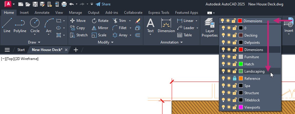
- Click View tab > Palettes panel > Blocks.Find
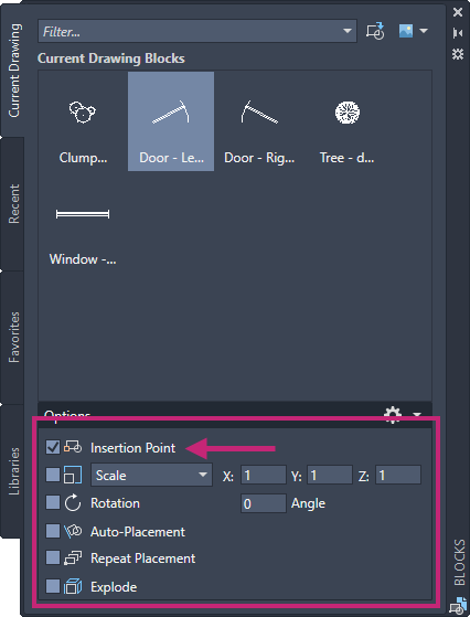
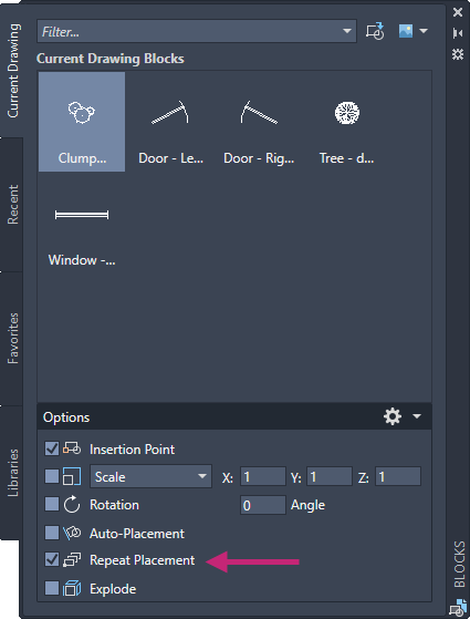
On the Blocks palette, under the Options section, clear all check boxes except for Insertion Point and click Insertion Point, if it is not already checked.
On the Blocks palette, Current Drawing tab, click Clump of Trees or Bushes - plan.
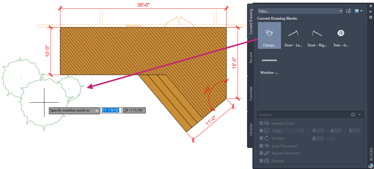
At the Specify insertion point or [Basepoint/Scale/Rotate]: prompt, specify a point below the lower-left corner of deck.
On the Blocks palette, under the Options section, click Repeat Placement.
Repeat Placement should now be checked.
On the Blocks palette, Current Drawing tab, click Tree - deciduous - plan.
At the Specify insertion point or [Basepoint/Scale/Rotate]: prompt, specify two points to the right of the deck.
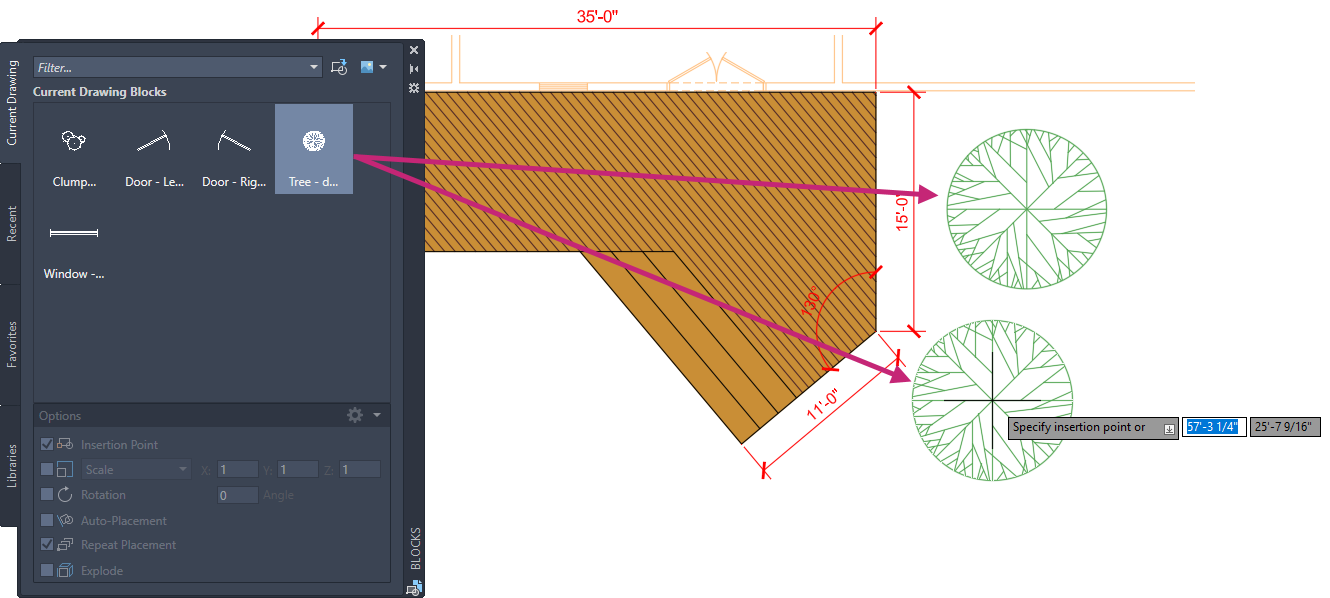
Press Esc or Enter to end inserting the block.
- On the ribbon, click View tab > Palettes panel > Blocks to close the Blocks palette.Find
You can also click the Close button on the Blocks palette's title bar.
- On the Quick Access toolbar, click Save.Find
Exercise 9: Plot the deck design
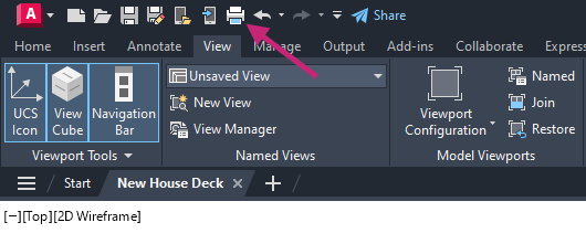
Plot/print the deck design to a PDF file so that others without AutoCAD access can see the design.- On the Quick Access toolbar, click Plot.Find
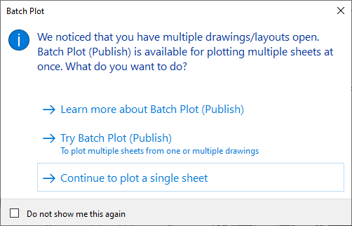
If the Batch Plot task dialog box is displayed, click Continue to Plot a Single Sheet.
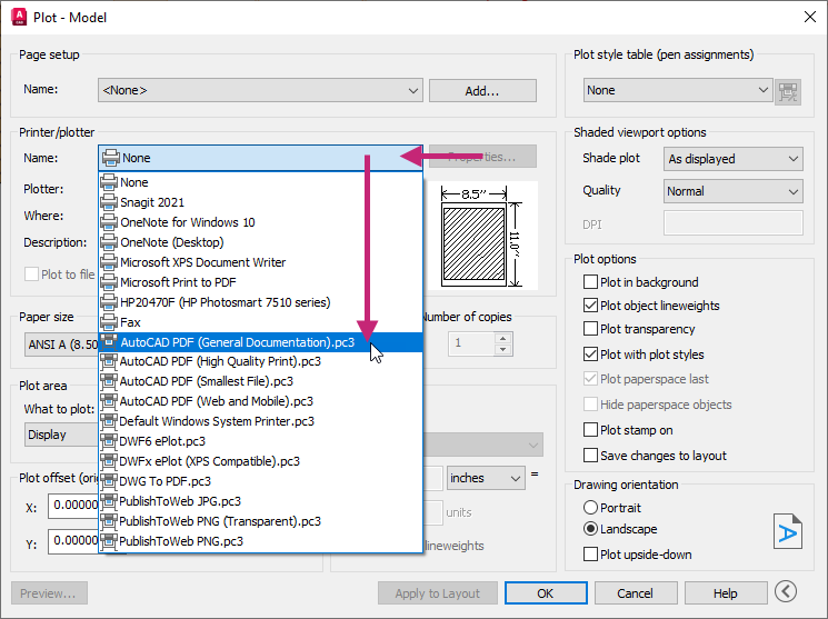
In the Plot - Model dialog box, under Printer/Plotter, click the Name drop-down list and choose AutoCAD PDF (General Documentation).pc3.
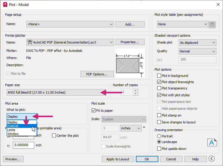
Under Paper Size, click the drop-down list and choose ANSI Full Bleed B (17.00 x 11.00 Inches).
Under Plot Area, click the What to Plot drop-down list and choose Extents.
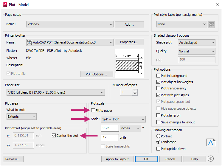
Under Plot Offset (Origin Set to Printable Area), select Center the Plot to turn the option on.
Under Plot Scale, clear Fit to Paper, and then click the Scale drop-down list and choose 1/4" = 1'-0".
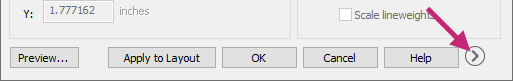
Click More Options to expand the dialog box.
Under Plot Style Table (Pen Assignments), click the Plot Style Table drop-down list and choose monochrome.ctb.
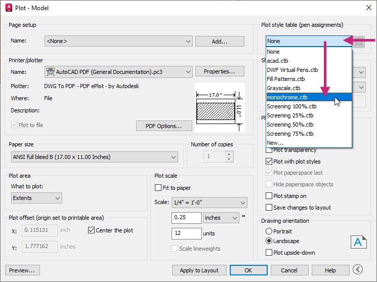
In the Question message box, click No.
Under Drawing Orientation, select Landscape.
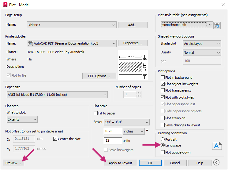
Click Apply to Layout to save the changes made to the plot settings and then click Preview.
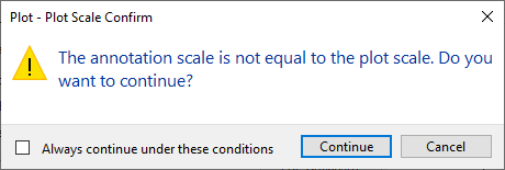
If the Plot - Plot Scale Confirm message box is displayed, click Continue.
In the Preview window, click and drag to increase and decrease the size of the preview. Right-click and use the shortcut menu to switch between the Zoom and Pan tools.
Press Esc or click Close Preview Window to return to the Plot dialog box.
In the Plot - Model dialog box, click OK.
If the Plot - Plot Scale Confirm message box is displayed, click Continue.
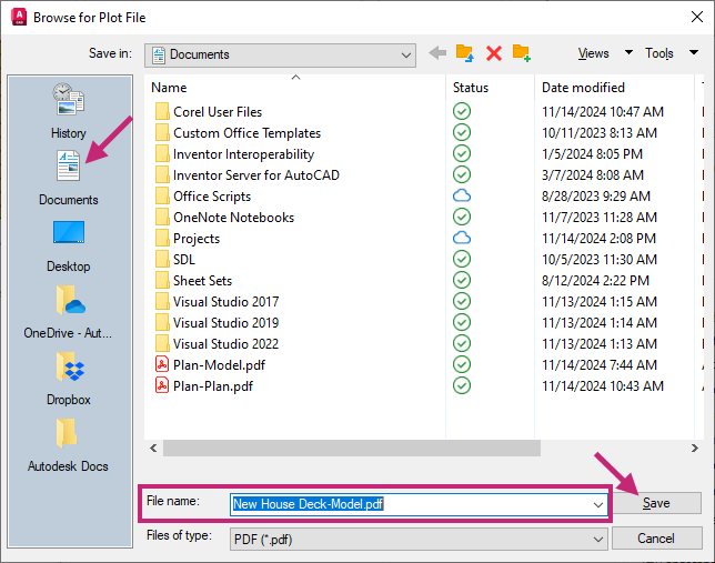
In the Browse to Plot File dialog box, browse to the Documents folder or a different location, and then provide a filename for the PDF file. Click Save.
Review the PDF file if it automatically opens, otherwise open and review the file from Windows File Explorer.
Return to AutoCAD.
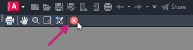
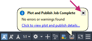
On the status bar, close the Plot and Publish Job Complete notification.
- On the Quick Access toolbar, click Save.Find
Summary
Congratulations on finishing the exercise! You've made great progress in mastering AutoCAD's essential tools and techniques. By completing exercises, like the "Architectural Design: House Deck," you are well on your way to learning key design methods.
You have learned how to open and create drawings, modify 2D objects, use layers, apply hatches and fills, add annotations, center marks, and dimensions, insert blocks, and plot drawings to PDF files. These skills are crucial for creating precise and confident designs.
As you continue to practice and apply these techniques, you'll find yourself more proficient and capable in your AutoCAD projects. Remember, the key to mastery is consistent practice and application. Keep exploring, learning, and designing with confidence!
For more information on the concepts covered in the exercises of this topic, see: