
Issue:
How to setup cyclic symmetry in Inventor Nastran.
Solution:
Cyclic symmetry occurs when the geometry, loads, constraints, and results of a partial model can be copied around an axis to give the complete model. A typical example is a fan or turbine blade. If the loads on the blades and geometry repeat, only one blade needs to be modeled instead of the entire hub and all of the blades. See Figure 1. The result is a smaller analysis which takes less time to solve and consumes less disk space.
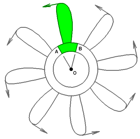
Figure 1: Cyclic Symmetry Example. The highlighted section, including the load, can be copied 7 times about axis O to create the full model.
Cyclic symmetry forces the radial, tangential, and axial displacements at one face (A in Figure 1) to match the displacements on the opposite face (B in Figure 1). The equal displacements are enforced using Multi-Point Constraints (MPCs), which are automatically defined by the analysis.
Cyclic symmetry cannot be used when the results are not cyclically symmetric. This type of result typically occurs in natural frequency (modal) analyses, where some of the mode shapes are cyclically symmetric and some are not. Using cyclic symmetry filters out some of the valid modes. The same is true for vibration analyses, which are based on modal results.
The basic steps for setting up a cyclic symmetry boundary condition are as follows:
- Decide where the cyclic symmetry faces are located. The cut faces need to be straight planes that pass through the center of rotation. The plane can consist of any number of surfaces. Though the meshes do not have to match, the geometry of the symmetry cross sections (area, length, width, and so on) must be the same, except for their rotational position around the axis of symmetry.
Although any cut through the part that results in a cyclic symmetry condition is acceptable, the cut that results in the fewest number of nodes on the boundary/cutting faces is generally best. Figure 2 shows two examples. - Apply loads and boundary conditions as normal. The model needs to be statically stable in all six directions—three translations and three rotations (when applicable). Cyclic symmetry does not prevent motion in any direction; it merely forces radial, tangential, and axial displacement components on one cyclic symmetry face to be equal to the corresponding components on the matching symmetry face. However, radial rigid-body motion is indirectly impeded due to the fact that the parts would have to stretch or compress circumferentially in order to move radially.
Frequently, the modeled parts are attached to something not included in the model, such as a shaft or hub. In this situation, the displacement of the model represents the motion of the part or assembly relative to the shaft or hub. Therefore, the boundary conditions at the attachment to the shaft or hub would be fully fixed. - Define a cylindrical coordinate system with the Z axis on the rotation axis of the model. (Coordinate systems are the last branch of the Nastran Model Tree.)
- Edit the analysis. Do the following on the Options tab:
- Check the box to include cyclic symmetry.
- Choose the cylindrical coordinate system.
- The tolerance is used to find nodes that are on the symmetry plane. The tolerance value entered has no dimensions. The value times the model reference dimension determines the tolerance in units of length. (The model reference dimension is the diagonal of the rectangular prism that encloses the model.)
(a) 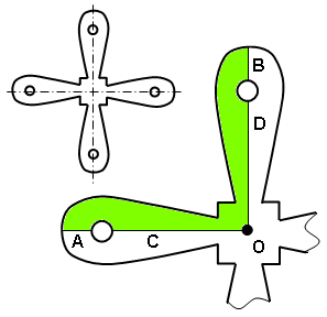 |
(b) 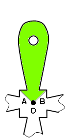 |
Figure 2: Sample cuts to create a cyclic symmetry model.
- Option 1. The inset shows the full model. The shaded portion is the model used in cyclic symmetry. Each symmetry plane is comprised of two model surfaces (A and C, for one; B and D for the other).
- Option 2 results in a much smaller pair of symmetry faces A and B, and therefore likely a significantly smaller number of nodes along those symmetry faces.