This item appears in the model tree just after Nodes. The total number of elements in the model is shown at the right end of the heading (such as, Elements 573). The Elements item appears in the model tree whether the mesh has been generated or not, with zero (0) shown for the number of nodes in an unmeshed model.
When you right-click on Elements, the following options are available from the context menu:
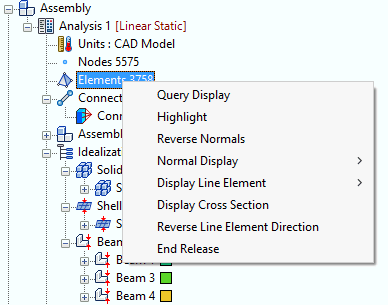
- Query Display: When this option is toggled on, it allows for real-time interrogation of elements in the model. Query Display for elements can also be accessed using the Query Display tool bar.
- Highlight: The highlight option allows you to highlight a set of elements in order to identify their locations and/or properties. There are two ways you can specify the nodes to highlight:
- Select the elements graphically by clicking them one-by-one on the model.
- If the Element IDs are knows, type them into the
Entity ID field, using a space or comma to separate multiple IDs. Then, click
ADD.
In either case, the selected or typed elements appear n the Selected Entities list box. The Highlight Elements dialog is pictured below:
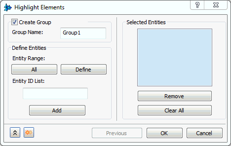
You can include items in the Selected Entities box in a new Element Group by clicking the Create Group checkbox. Groups provide a convenient means of re-selecting multiple items at a later time.
- Reverse Normals:
Reverses the direction of the mesh element normal. This option is only available when using shell elements. You can select between two options under
Display Options.
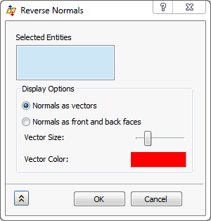
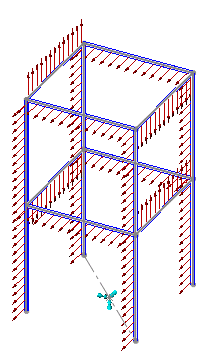
- Normals as vectors: The direction of the normal is depicted with a vector. The Vector Size slider allows you to select how large the vector will be displayed on screen. Clicking on the color swatch under Vector Color allows you to select which color the vectors will be displayed as.
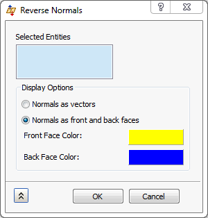
- Normals as front and back faces: The direction of the normal is depicted using colors. The
Front Face Color dictates the positive direction while the
Back Face Color dictates the negative direction. The colors can be changed in a similar manner as described in the preceding bullet.
-
Normal Display:
- Off: Neither vectors or front/back face colors are displayed.
- Vector: Displays the vectors.
- Color: Displays the front/back face colors.
- Display Line Element: Has two options for line elements to display.
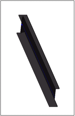
- Orientation: This displays the elemental orientation vector (Elemental Y axis) for 1D line elements. This is useful in determination of the orientation of a 1D cross section.
- Direction: This displays the elemental X axis for 1D elements. This is useful for determination of the orientation of a 1D cross section.
Orientation Vectors
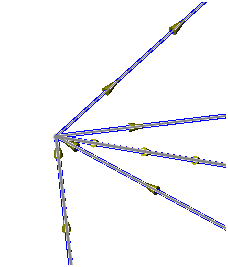
Element Direction Vectors
- Display Cross Section: This is used for 1D and 2D elements (Beams/Bars and Shells). The geometry must be meshed and a property assigned to the particular mesh in order to view the cross section. This is used to see the thickness of plate elements and the cross section of 1D beam elements defined using the cross section definition.
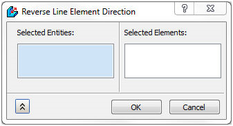
- Reverse Line Element Direction: This is used to help in reversing the orientation and x-axis of line elements.
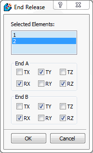
- End Release: End release is supported for line elements. Beam element has 6 DOF, there are special situations like rotating shaft or hinge joint where rotation or translation in a specific direction is free. End release is a special command to release one or more DOF of beam.
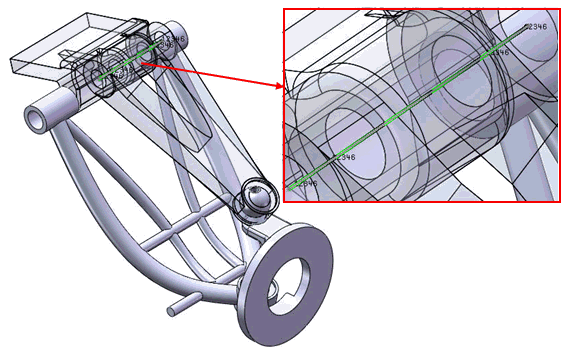
Suppose pin of the hinge is simulated by beam element. End release (rotation along vertical axis) would be helpful in simulating the reality.
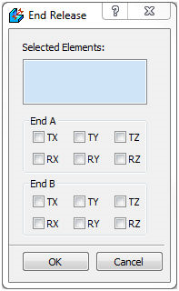
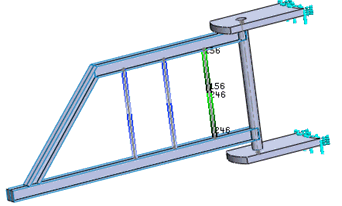
End release for each element can be defined by selecting the elements from the list. For example, select two elements from the model and select 1st element and check Tx, Ry and Rz for both End A and End B. Notice the selected DOF is highlighted in numbers (1-6) at the element in the model.
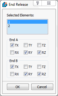
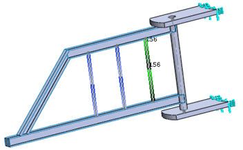
Now, select 2nd element and check Ty, Rx and Rz for both End A and End B. Notice the selected DOF is highlighted in numbers (1-6) at the element in the model.