
Control the display of probe paths and path errors in the CAD view.
 Ribbon: File tab
  Options Application Options Probe Path
The following options are displayed.
- On — Automatically identify problems in the probe paths of all documents.
Clear the check box to disable probe-path verification.
Tip: Use Home tab > Probe Path panel > Verification, to control verification for individual documents. - Contact point symbol — Specify how the contact points of a probe path are represented in the CAD view.
- Fault symbol — Specify how probe-path faults are represented in the CAD view.
- Ignore missing contact points — Disregard missing contact points during probe path verification.
Clear to identify missing contacts with icons displayed in the inspection sequence and the CAD view.
Tip: When you create the inspection sequence without a model, select this box to prevent each contact point from being reported as missing. - Head clearance — Clearance distance for the probe.
Use this setting to manage variations between the CAD model and the part in the probe-path verification process.
- Probe assembly clearance — Clearance distance between the probe assembly and the part.
Use this setting to compensate for variations between the CAD model and the physical part in the probe-path verification process.
- Use auto-calculated clearance values for active stylus — Use the automatically calculated clearance distances. Clear to specify distances:
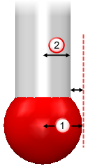
- Active stylus clearance during move — Clearance distance for intermediate moves that is less than the specified approach and retract distances.
- Active stylus shank clearance during measure — Clearance distance for measure moves that is less than the difference between the stylus radius
 and the stem
 .
.
Note: For auto-calculated clearance values, PowerInspect calculates the clearance required for the stylus using the Probe Assembly Clearance, the approach and retract distances, the measuring device, and the type of move. - Machine parts clearance — Clearance allowed for machine-part collisions.
For example, if set to 2.000 mm, a collision is detected if the distance between a moving machine-part and the part being measured, or between a moving machine-part and another moving machine-part, falls below 2.000 mm during simulation.