Issue:
How to model a custom thread in Fusion?
Solution:
To create a custom thread try one of the following methods:
Thread Command
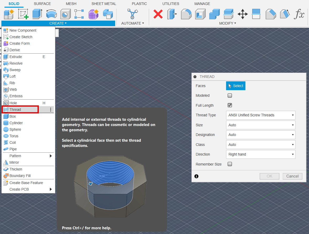
Create Menu.
Select Thread command.
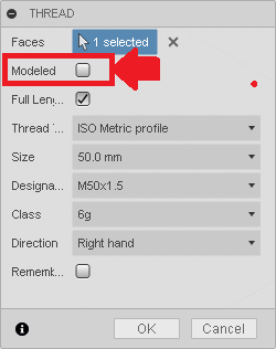
Set desired characteristics in the Thread dialog.
Note: if two threaded holes intersect, the thread command will likely fail when creating the second thread. Try one of the following options if this is the case.
Hole Command
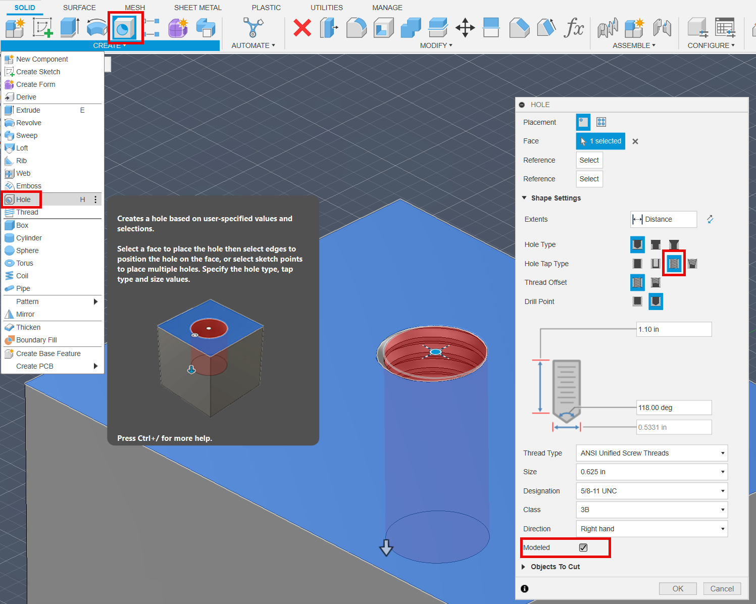
Create Menu.
Select Hole command.
Click on a face or on a sketch point.
Set desired characteristics in the Hole dialog.
- Coil Command
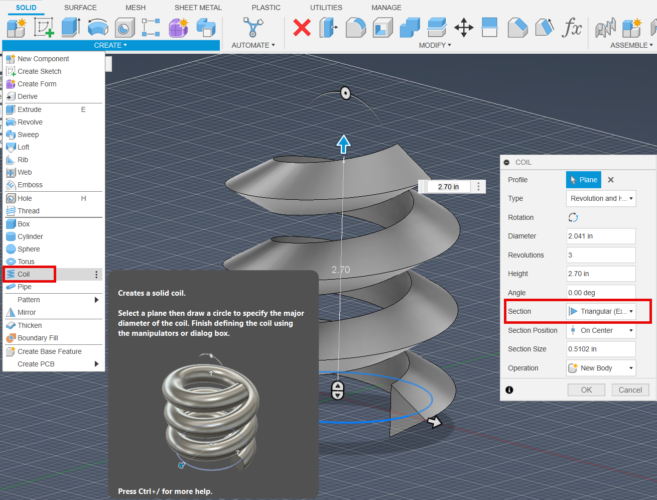
Create Menu.
Select Coil command.
Choose the plane to start the coil on.
Create the coil with the desired settings.
At this point there are two options;
A. Create the proper threads with the Coil itself and use the Combine Cut command with the Coil as the tool body, for these steps see Combine Command set to Cut operation which follows.
B. Use the path created by an edge in the created coil to act as the path in a sweep command.
Go to the Construct Menu in the Tool bar.
Select the Plane Along Path command.
Select the desired edge of the coil as the path.
Create a sketch on the new plane along the path.
Draw the desired thread profile.
Finish the sketch.
Select the Sweep command.
Sweep the thread profile sketch along the path of the edge of the coil.
This can be used to cut or create the threads.
Note: Sometimes, the "Path + Guide Surface" option will need to be used within the Sweep command to keep the modeled threads from twisting.
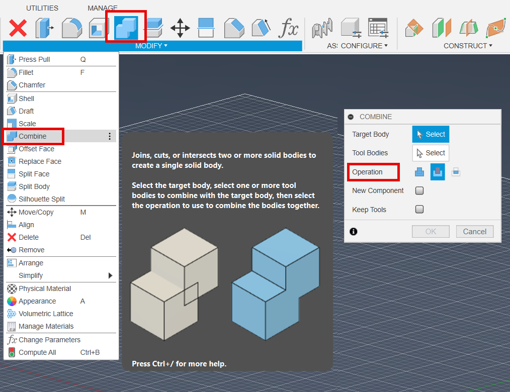
- Combine Command set to Cut operation
- Create an opposite version of your desired threads to act as a tool body to cut the threads into your target body. For example if you need to create threads in a hole then create a "bolt" or "stud" that has the threads on them already. Alternatively, download a bolt with the desired threads with the Insert McMaster-Carr command.
- Position the tool body on the tool body as needed.
- Modify Menu.
- Select Combine command.
- Select Target body.
- Select Tool body.
- Set the Operation to Cut (or Join if you are combining threads from the preceding coil command to a body).
- Click Ok.
Note: The Modeled option will generate 3D geometry that can be used instead of a coil to create the guide surface. However this may be best suited for differing profiles rather than pitch.