Stock tab reference
 Stock tab settings
The toolpath is calculated based on the size of the stock around the model being machined. An accurate description of the stock helps to give better toolpath results. Stock and fixtures are considered when simulating the toolpath, and by some machining toolpath strategies.
Mode
The Mode drop-down list lets you choose from different stock options:
- Fixed size box - Create a rectangular stock boundary of a specified size.
- Relative size box - Estimate a rectangular stock boundary around the part with offset options.
- Fixed size cylinder - Create a cylindrical stock boundary of a specified size.
- Relative size cylinder - Estimate a cylindrical stock boundary around the part with offset options.
- Fixed size tube - Create a tubular stock boundary of a specified size.
- Relative size tube - Estimate a tubular stock boundary around the part with offset options.
- From solid - Select a solid body to use as stock.
- From bounding solid - Select a bounding solid to use as stock.
- From preceding setup - Use stock from the previous setup (rest machining).
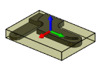
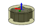
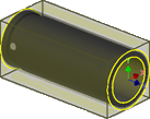
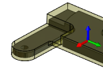
Fixed size box
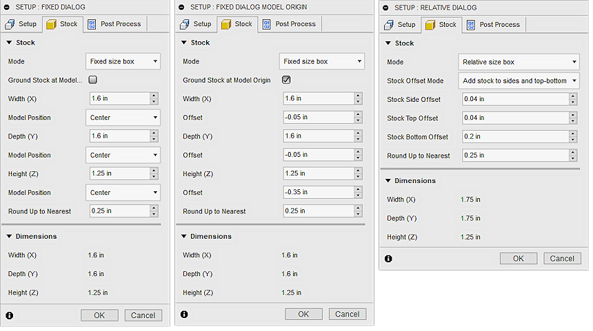
The Fixed size box mode lets you enter precise XYZ values to specify the width, depth, and height of your stock. You can position the stock in reference to the left, right, front, back, top, bottom or the Design Origin of the model. Model Design Origin may be different from the Setup WCS Origin.
Ground stock at model origin
When selected, the stock is positioned relative to the Model Origin. When deselected, you can use Model Position drop-down lists to position the stock.
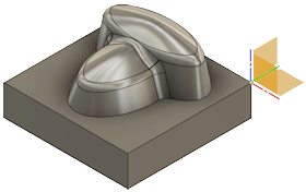
To see the Model Origin, go to the Browser, expand Models and change the visibility ![]()
![]() of Origin. Model Design Origin may be different from the Setup WCS Origin.
of Origin. Model Design Origin may be different from the Setup WCS Origin.
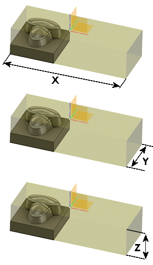
Width (X), Depth (Y), and Height (Z)
These represent the raw stock block size and are always specified with positive values.
Model position (when Ground stock at model origin is deselected)
Offset values can be positive or negative and are used to shift the raw stock relative to the selected reference position.
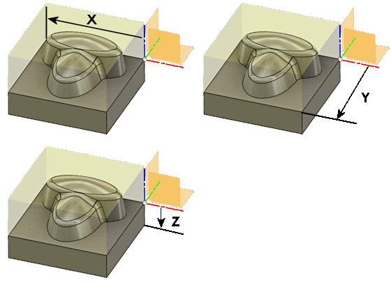
Model position X
- Offset from left side (-X) - Reference to the furthest X negative position
- Center - Reference to the center of the model in X
- Offset from right side (+X) - Reference to the furthest X positive position
- Offset from the model origin - Reference to the X origin of the Model Design
Model position Y
- Offset from back side (+Y) - Reference to the furthest Y positive position
- Center - Reference to the center of the model in Y
- Offset from front side (-Y) - Reference to the furthest Y negative position
- Offset from the model origin - Reference to the Y origin of the Model Design
Model position Z
- Offset from top (+Z) - Reference to the furthest Z positive position
- Center - Reference to the center of the model in Z
- Offset from bottom (-Z) - Reference to the furthest Z negative position
- Offset from the model origin - Reference to the Z origin of the Model Design
Offset (when Ground stock at model origin is selected)
Offset values can be positive or negative and are used to shift the raw stock relative to the Model Origin.
Round up to nearest
Rounding up increment for the final stock size.
Relative size box

The Relative size box mode approximates the required stock size. Includes options to add stock to the top, bottom, and/or sides of the stock.
 |
 |
|
| No Additional Stock Actual Size. |
Added Stock Stock on all sides. |
Stock offset mode
Choose how to add stock to the part:
- No additional stock
- Add stock to sides and top-bottom - Symmetrical stock offset for all sides with unique values for top and bottom
- Add stock to all sides - Unique values for all sides of the part
Fixed size cylinder
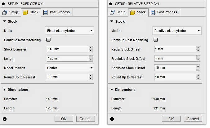
The Fixed size cylinder mode lets you enter precise values to specify the diameter and length of the stock. The Model Position drop-down menu offers options to help you better position your model relative to the stock.
Stock diameter
Specifies the diameter of the stock.
Length
Specifies the length of the stock.
Model position
- Offset from front - Positions the stock flush with the front face of the model
- Center - Centers the model within the cylindrical stock
- Offset from back - Positions the stock flush with the back face of the model
Relative size cylinder

The Relative size cylinder mode estimates a cylindrical stock boundary around the part. Includes options to offset additional stock around the part and to round up to a specified increment.
Radial stock offset
Additional amount to offset radially.
Frontside stock offset
Additional amount to offset on the frontside of the model.
Backside stock offset
Additional amount to offset on the backside of the model.
Fixed size tube
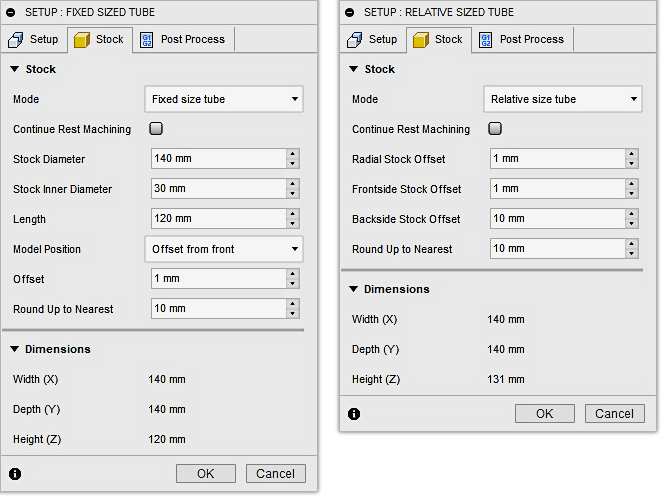
The Fixed size tube mode lets you enter precise values to specify the inside diameter (ID), outside diameter (OD) and length of the stock. The Model Position drop-down menu offers options to help you better position your model relative to the stock.
Stock diameter
Specifies the outer diameter of the tube stock.
Stock inner diameter
Specifies the inner diameter of the tube stock.
Length
Specifies the length of the stock.
Model position
- Offset from front - Positions the stock flush with the front face of the model
- Center - Centers the model within the tube stock
- Offset from back - Positions the stock flush with the back face of the model
Relative size tube

The Relative size tube mode estimates a tubular stock boundary around the part. Includes options to offset additional stock around the part and to round up to a specified increment.
Radial stock offset
Additional amount to offset the ID and OD radially.
Frontside stock offset
Additional amount to offset on the frontside of the model.
Backside stock offset
Additional amount to offset on the backside of the model.
From solid

The From solid mode lets you select any solid body in a multi-body part, or from a part file in an assembly. Useful for defining stock from a forging model, where the part is semi-formed prior to machining.
Stock solid
Click Select to choose the solid body to use as stock.
From bounding solid
The From bounding solid mode lets you select a bounding solid to use as stock.
Bounding solid
Click Select to choose the bounding solid to use as stock.
From preceding setup
The From preceding setup mode uses stock from the previous setup. This enables rest machining operations.
Continue rest machining
When selected, you can perform Rest Machining operations based on the previous Setup (Turning Operation type only).
For more information, watch the Create a setup in Fusion for turning video.
