Utility category - Stingray Shader Node Reference
Description
This category contains useful nodes that alter texture coordinates and color values in various ways.
Nodes
| Inputs | |||||
vector3 | Base |
|
The first normal map to blend in. | ||
vector3 | Detail |
|
The second normal map to blend in. | ||
| Outputs | |||||
Out | auto |
The result of blending the two input normal maps together. | |||
| Options | |||||
| Method |
The blending method used to combine the values from the two maps. See this page for a discussion of normal map blending, and for details on these options.
| ||||
NOTE: To set the options listed above, select this node in the shader graph and open the Property Editor panel in the Stingray Editor.
| |||||
For example, you could use this node to add high-frequency small-scale detail to a less detailed base surface.
NOTE: If the inputs to this node are coming from sampled textures, make sure that the Encoding option for those sampling nodes is set to Normal Map.
Node definition in file: core/shader_nodes/blend_normals.shader_node
| Inputs | |||||
vector3 | Position |
|
The world position | ||
vector3 | Normal |
|
The world normal | ||
vector3 | Color |
|
A color input used to perturbe the normal | ||
scalar | Scale |
|
A pertubation intensity value (defaults to 0.1) | ||
| Outputs | |||||
Out | auto |
The perturbed normal | |||
Node definition in file: core/shader_nodes/bump.shader_node
 |
Adjusts the opacity of a pixel based on the distance between the pixel being shaded and the pixel behind it.
|
| Inputs | |||||
scalar | Opacity |
|
The input opacity of the pixel being shaded. Values closer to 0 make the surface more transparent; values closer to 1 make the surface more opaque. Default value: 1.0. | ||
scalar | Fade Distance |
|
The distance behind the pixel being shaded at which its opacity begins to apply, expressed in meters. Default value: 1.0. | ||
| Outputs | |||||
Out | scalar |
The adjusted opacity value of the surface. | |||
| Pre-requisites | Output nodes | This node can only be used in a shader graph that contains the following output node: | |||
Use this node in order to make a transparent surface in which closer objects appear more clearly than faraway objects.
Node definition in file: core/shader_nodes/depth_fade.shader_node
| Inputs | |||||
vector3 | Color |
|
The input color that will be desaturated. | ||
scalar | Amount |
|
The blend weight between the original input color and its fully grayscale equivalent. A value of 0 leaves the input color unaltered. A value of 1 (or higher) produces a fully grayscale final result. Default value: 1. | ||
vector3 | Luminance |
|
Determines the brightness of each channel in the desaturated color. This allows you to compensate for the way the human eye perceives the relative lightness of different colors. This value is expressed as a coefficient for each color channel. To determine the grayscale color, the value of each color channel is multiplied by the coefficient for that channel, and the three channel values are added. For example, setting a value of (1, 0, 0) makes red areas in the original image come through as white, while blue and green areas come through as black. Some common luminance settings are: | ||
| Outputs | |||||
Out | auto |
The RGB values for the desaturated color. | |||
Node definition in file: core/shader_nodes/desaturation.shader_node
| Inputs | |||||
scalar | Discard |
|
The value to test. | ||
auto | Input |
|
The value we want to output if Discard is false. | ||
| Outputs | |||||
Out | auto |
The output value or values produced by this node. | |||
Node definition in file: core/shader_nodes/discard.shader_node
| Inputs | |||||
scalar | Minimum |
|
When the Method option is set to Use Min/Max, this setting defines the minimum value used in the calculation. Default value: 0.8. When the Method option is set to Use Exponent, this setting is not used. | ||
scalar | Maximum Exponent |
|
When the Method option is set to Use Min/Max, this setting defines the maximum value used in the calculation. When the Method option is set to Use Exponent, this setting specifies the exponent value used in the calculation. Default value: 1. | ||
vector3 | Normal |
|
Sets a custom surface normal for the calculation. | ||
| Outputs | |||||
Out | scalar |
The result of the Fresnel calculation for the surface. | |||
| Options | |||||
| Method |
Determines the method of calculation used by the shader. | ||||
NOTE: To set the options listed above, select this node in the shader graph and open the Property Editor panel in the Stingray Editor.
| |||||
You can use this effect to change the color or reflectance of a surface when seen from different angles.
Node definition in file: core/shader_nodes/fresnel.shader_node
| Inputs | |||||
vector3 | HSV |
|
The input HSV color. | ||
| Outputs | |||||
Out | auto |
The RGB equivalent of the input value. | |||
Node definition in file: core/shader_nodes/hsv_to_rgb.shader_node
| |
Chooses between one of two input values, depending on the value of an option set on the node in the Property Editor.
|
| Inputs | |||||
auto | Enabled |
|
The output value to choose when the Option is set to Enabled. | ||
auto | Disabled |
|
The output value to choose when the Option is set to Disabled. | ||
| Outputs | |||||
Out | auto |
Either the Enabled or Disabled input, depending on the Option value. | |||
| Options | |||||
| Option |
Determines which input value this node returns. | ||||
NOTE: To set the options listed above, select this node in the shader graph and open the Property Editor panel in the Stingray Editor.
| |||||
You can use this node to switch easily between two different graph chains.
Note that you can only adjust this option inside the shader graph; it is not exposed as a property on the material. Therefore, it cannot be modified in the game at runtime, or in the Property Editor when the material is selected. If you need to be able to switch between the input chains in response to values set on the material either in the Property Editor or at runtime, use the Math > If node instead.
Node definition in file: core/shader_nodes/option.shader_node
| Inputs | |||||
vector2 | UV |
|
The input texture coordinates before being panned. | ||
scalar | Time |
|
The current system time. Required. You can get this value from the Input > Time node. | ||
scalar | Speed U |
|
The speed at which the texture should appear to move along the U axis. Default value: 0.33 | ||
scalar | Speed V |
|
The speed at which the texture should appear to move along the V axis. Default value: 0.33 | ||
| Outputs | |||||
Out | auto |
The input UV coordinates after being panned. | |||
When you sample a texture at the UV coordinates produced by this node, the texture appears to be panning across the surface at a speed specified by the Speed U and Speed V parameters.
Node definition in file: core/shader_nodes/panner.shader_node
| |
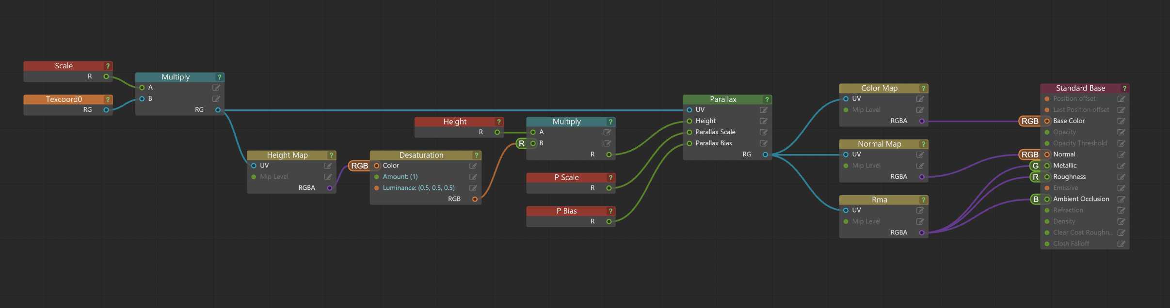
This node gives a surface the illusion of depth by shifting the UV coordinates of the pixels being shaded according to the height of the pixels from the surface and the camera's point of view.
|
| Inputs | |||||
vector2 | UV |
|
The input UV that will be adjusted by the height value. | ||
scalar | Height |
|
The height of the pixel being shaded, usually drawn from a height map or bump map texture. | ||
scalar | Parallax Scale |
|
The amount of apparent deviation the heightmap causes in the surface. Default value: 0.04 | ||
scalar | Parallax Bias |
|
A constant amount subtracted from the height in order to cause "lower" pixels to appear sunken below the surface plane. You will typically want this value to be about half of the parallax scale value, so that the median of the low and high points will lie approximately on the level of the original mesh surface. Default value: 0.02 | ||
| Outputs | |||||
Out | auto |
The output value or values produced by this node. | |||
| Pre-requisites | Output nodes | This node can only be used in a shader graph that contains the following output node: | |||
This means that "lower" pixels can be occluded by "higher" pixels.
The technique used by this node is known as "parallax mapping" or "bump mapping". It is similar to normal mapping, except that instead of using a map that contains the normal vectors of a surface, it typically uses a greyscale map (a scalar input value) that determines the height of the surface. Lighter color values or higher scalar values are "higher" in relief, and darker color values or lower scalar values are "lower".
For example:
 Visit the AREA to download this sample parallax shader and watch our tutorial on Parallax Mapping in Stingray.
Node definition in file: core/shader_nodes/parallax.shader_node
| Inputs | |||||
vector3 | RGB |
|
The input RGB color. | ||
scalar | Hue |
|
An optional hue value that will be added to the value produced by the conversion in order to adjust the result. | ||
scalar | Saturation |
|
An optional saturation factor that will be multiplied with the value produced by the conversion in order to adjust the result. | ||
scalar | Brightness Value |
|
An optional brightness factor that will be multiplied with the value produced by the conversion in order to adjust the result. | ||
| Outputs | |||||
Out | auto |
The HSV equivalent of the input color, adjusted by the Hue, Saturation and Brightness / Value inputs if specified. | |||
Node definition in file: core/shader_nodes/rgb_to_hsv.shader_node
| Inputs | |||||
vector2 | UV |
|
The input texture coordinates before being rotated. | ||
scalar | Time |
|
The current system time. Required. You can get this value from the Input > Time node. | ||
vector2 | Pivot |
|
The UV coordinates that should be the center of the rotation. Default value: 0.5 0.5 | ||
scalar | Speed |
|
The speed at which the texture should appear to rotate. Default value: 0.1 | ||
| Outputs | |||||
Out | auto |
The input UV coordinates after being rotated. | |||
When you use the UV coordinates produced by this node to sample a texture, the texture rotates across the surface at a speed specified by the Speed parameter around a pivot point specified by the Pivot parameter.
Node definition in file: core/shader_nodes/rotator.shader_node