Click
Options
 on the
Inventor Nesting ribbon to open the Options dialog box.
Display Tab
Adjust values for how information is displayed in the application window. Changes are previewed at the bottom of the dialog box.
- Nests
-
- Font: Select a font and size for text in the application window. Only fonts that are supported by all Inventor Nesting languages are available.
- Color: Adjust colors for each type of nest element that is shown in the application window. Make sure to use colors that contrast with the background for best visibility.
- Property Name: The property descriptor; for example, "Sheet name," "Material", and so on
- Property Value: The name assigned to the property; for example, "Sheet1", "Material ID 2", and so on
- Geometry Default: Shape color, if the shape does not have one
- Dimensions: The horizontal and vertical lines indicating the size of the sheet
- Sheet Border, Remnant, and Trim: Element borders
-
- Direction Spacing: Adjust the distance, in X and Y values, between sheets in the application window.
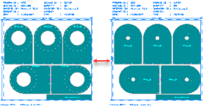
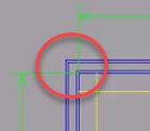
- Sheet Border: Show borders and dimension lines. If a stack of two or more is present, it is indicated by two borders overlapping each other, no matter how big the stack is.
- Direction Spacing: Adjust the distance, in X and Y values, between sheets in the application window.
- Show dimensions and which kind to show.
- Show header information above each sheet. You can select the number of columns to use, as well as which properties to include (Sheet name, material, and so on).
- Show additional information including a legend under each sheet, the identifier of each shape source, and, to the left of each nest, a list of properties for all the sheets in that nest. You can select which properties to include (Nest name, Nesting efficiency, and so on).
- Show etch information.
- Sources
-
- Direction Spacing: Adjust the distance, in X and Y values, between unnested shapes in the application window.

- Display Tolerance: Set the quality of shape edges to optimize performance.
Display Tolerance: 0.000393701in Display Tolerance: 0.1in 

- Fill Non-Nestable Contours: In the application window, if you have a shape that contains contours – for example, holes – that are flagged in the configuration file as unnestable, those contours are filled.
Not Filled Filled 

This does not apply in Wireframe mode.
- Sources Arranged By Material: Arranged sources in the application window according to material.
- Representation: The default view of source shapes in the application window (2D, 3D Extruded, and so on).
- Direction Spacing: Adjust the distance, in X and Y values, between unnested shapes in the application window.
Extract Tab
Use this tab to manage configuration files. A configuration file is a customizable set of instructions on how to extract files. For example, it can define that the fifth layer of a DXF file contains geometry that should be excluded from the nest. These mappings are retained by Inventor Nesting and included in exported nest data (such as MSI files). Inventor Nesting includes a default configuration file. You cannot edit this file, but you can create customized versions of it to match your workflow. If you consistently use the same mappings in your work, you likely will not need to make changes to a configuration file once you create one that works for you.
- Active Configuration Folder
- The folder where you would like to store configuration files so that they can be detected by
Inventor Nesting and loaded into a drop-down menu. If you do not change this, the default installation location is used.
 Browse: Change the folder.
 Reveal: Show the folder in Windows Explorer.
 Refresh: If the configuration file has been modified on disk while the Options dialog box is open, this refreshes the dialog box with the latest changes.
- Active Configuration File
- The configuration file to use when extracting files. The default file installed with
Inventor Nesting is
C:\Users\Public\Documents\Autodesk\Nesting Utility <version> \Translation\DefaultConfiguration.cgf. The drop-down list includes the default file and any files you create in your configuration folder.
- Edit: Make changes to the configuration file using the Extract Configuration Editor dialog box.
- Reset
- Restores the default settings and loads the default configuration file.
Export Tab
The Export tab is identical to the Extract tab, but used to manage configuration files for exporting to MSI or DXF files. Click Edit to make changes to the configuration file using the Export Configuration Editor dialog box.
Prompting Tab
- Auto-Save Nest Results If Idle
- After a nest is calculated, it needs to be saved to be visible in the application window. Select this so that results are automatically saved as long as you are not doing something else in Inventor Nesting. If you deselect this, or if the save gets interrupted, right-click the nest in the Inventor Nesting browser and click Save Results.
- Prompt At Nest Completion
- After a nest is calculated, this prompts you to save it. If Auto-Save Nest Results If Idle is enabled, this only happens if the save was prevented from taking place because you were doing something else in Inventor Nesting.
- Display Nest Calculation Warning And Error Prompts
- If there are errors during nest calculation—for example if packaging is too small to nest any parts—this enables error messages to be displayed.
Browser Tab
- Show Shape Name
- In the browser, show the name of shapes alongside their corresponding items.

- Show Sheet Quantity
- In the browser, show the quantities of sheets that will be used in nests.

