Creates curves-on-surface at the boundaries of out-of-draft areas.
Some manufacturing processes, such as injection molding, impose restrictions on the shape of an object. To avoid problems, you should understand the following concepts:
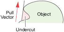
- The mold parts are pulled away from the object in a straight line, the pull vector.
- If the sides of the mold are too steep, the object cannot leave the mold. As well, the object cannot leave the mold if the mold undercuts itself.
- The minimum allowable angle between the sides of the mold and the pull vector is the draft angle.
- If part of a surface has an angle less than the draft angle, it is said to be out-of-draft.
- Draft lines are the boundaries between in-draft and out-of-draft regions.
- The parting line sits at a draft angle of zero degrees, and corresponds to the location where the mold separates.
Parting Line Control options
The options offer the ability to evaluate in-draft and out-of-draft regions along both directions of the pull vector, since a mold often separates in both directions. Positive and negative in-draft and out-of-draft regions of the surface, as well as tolerance regions are shaded different colors. Tolerance regions are "grain wash" zones that form part of the out-of-draft regions.
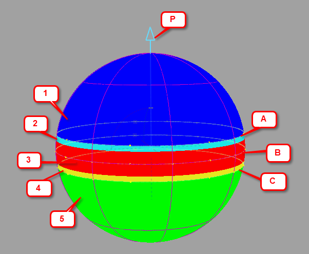 Output from the Parting Line tool showing both shaded display (1-5) and curves-on-surface (A-C). P = Pull direction. |
|
- Parting Line (0 degree)
- Check on this option to create a curve on the surface for a draft angle of 0 degree. This corresponds to the location where the mold separates.
This option is only available if Create Curves is checked on.
- Positive Draft Angle
-
Check on this option if you want to calculate the in-draft and out-of-draft regions for a draft angle given by the Positive Draft Angle number field, with respect to the pull vector.
If the angle between a surface point and the pull vector is less than this value, the surface point is out-of-draft, and is colored red.
If the angle between a surface point and the pull vector is more than this value, the surface point is in-draft, and is colored blue.
- Positive Tolerance Zone
- Displays a cyan tolerance region between the positive in-draft and out-of-draft regions. The tolerance value represents an angle measured in degrees. If the tolerance value is 0, no tolerance region is displayed.
This option is only available if Shade Surfaces is checked on.
- Negative Draft Angle
-
Check on this option if you want to calculate the in-draft and out-of-draft regions for a draft angle given by the Negative Draft Angle number field, with respect to the negative (opposite) direction of the pull vector.
If the angle between a surface point and the direction opposite to the pull vector is less than this value, the surface point is out-of-draft, and is colored red.
If the angle between a surface point and the direction opposite to the pull vector is more than this value, the surface point is in-draft, and is colored green.
- Negative Tolerance Zone
- Displays a yellow tolerance region between the negative in-draft and out-of-draft regions. The tolerance value represents an angle measured in degrees. If the tolerance value is 0, no tolerance region is displayed.
This option is only available if Shade Surfaces is checked on.
- Link Values
- Check on this option if you want the negative draft angle and tolerance zone values to mirror the positive draft angle and tolerance zone values.
- Subdivision
-
The quality of the curve-on-surface projection, from 1 to 6. The higher the value, the more precise the result. Use low values for draft quality, use higher values for final results.
Vector Options
These options let you select the pull direction, that is the direction in which the object will be removed from its mold.
- X,Y, Z
-
Select one of these to specify a pull direction along that axis.
- View
-
Select this option to specify a pull direction normal to the current view. The vector is not drawn in the view windows.
If the current view is changed, click Refresh View Vector to update the vector.
- Picked
-
Selecting this option lets you specify the name of an existing vector in the Picked Vector field, or pick the vector in the view. This vector defines the pull direction.
- Manip
- This option is selected automatically when you update the pull direction by manually modifying the manipulator in the view.
- Refresh Vector
-
This button only appears if View is selected. Click it to update the vector if the view has been modified.
- Retain Vector
-
Click this button to create a vector construction object in the view windows. Unless you do this, the vector direction you specified is used by the tool, but you will not see and be able to re-use the vector.
Display Options
- Shade Surfaces
- Check on this option to shade the in-draft, out-of-draft and, optionally, tolerance zones, with different colors. This is the same functionality as the Draft Angle shading mode in the Modeling control panel.
- Create Curves
- Check on this option to create either curves-on-surface or visual curves for the draft line(s) and/or 0-degree line (parting line).
- Curve Type
-
If Create Curves is checked on, these two options become available:
Visual – Creates fast polylines. These lines are mainly for display purposes. Although you can pick them (to delete them, for example), you cannot use them to create geometry.
Geometry – Creates curves-on-surface. These curves are real geometry that can be edited and used to build further geometry.
- Display Tolerance
- When Visual is selected, this value defines the quality of the visual curves independently of the tessellation tolerance. This lets you set the visual tolerance to a smaller value to get better quality visual curves, without reducing the tessellation tolerance used for shading.
Control Options
- Create History
-
Save the history of the new curves-on-surface for later editing. If you turn Create History on, you can modify the surfaces and the curves-on-surface update.
- Auto Update
-
Update the curves-on-surface and shading as you change the values in the window.
Buttons
- Reset
- Resets all option values to their defaults.
- Update
-
When Auto Update is off, use this button to update the curves on surface and shading to correspond to the current options.
- Undo All
-
Undo all the changes made by the tool and return to the original surface.
- Next
-
Finish creating curves-on-surface and shading on the current surface and prompt for a new surface to evaluate.