Create curves-on-surface corresponding to highlights, iso-curvature lines, contours, horizon lines, or parting lines.
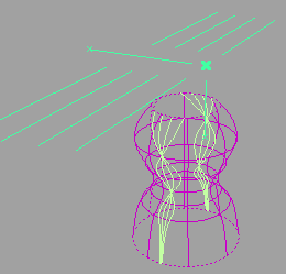
Create curves on surface from highlight data
To create curves-on-surface corresponding to highlight lines:
- Pick the surfaces on which you want to create curves-on-surface.
- Choose Evaluate > Surface Evaluate > Highlights

 .
. The Highlights control window opens and the highlight manipulator appears.
- Click the Go button.
Curves-on-surface are created.
- Set the following options in the option window:
- The Number of Lights you want to create highlights from.
- The Light Spacing (if there is more than one light) or the Light Width (if there is only one light).
- Set the Subdivision option from 1 to 6. The higher the number, the more precise the result. Use low values for draft quality, use higher values for final results.
The curves on surface update as the option values are modified. (If they do not, turn on Auto Update or click Update to create the curves-on-surface.)
The manipulator reflects the changes.
- Drag different handles on the manipulator to position and orient the light(s), or type exact values into the Light Origin, Light Direction, and Vector/Plane/Point fields of the Highlights window.
The curves on surface update.
- Click on additional surfaces to evaluate them, or deselect active surfaces.
- Click the Undo All button in the control window to remove the curves-on-surface.
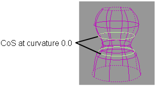
Create curves on surface from curvature data
To create curves-on-surface along lines of constant curvature:
- Pick the surfaces on which you want to create curves-on-surface.
- Choose Evaluate > Surface Evaluate > Curvature
 .
. The Curvature control window opens.
- Click the Go button.
Curves-on-surface are created.
- Set the following options in the control window:
- The Curvature Type.
- The Curvature Value at which you want to create curves on surface. For example, enter 0 to create curves-on-surface along inflection lines.
- Set the Subdivision option from 1 to 6. The higher the number, the more precise the result. Use low values for draft quality, use higher values for final results.
The curves-on-surface update as the option values are modified.
If Auto Update is off, click Update to create the curves-on-surface.
- Click on additional surfaces to evaluate them, or deselect active surfaces.
- Click the Undo All button in the control window to remove the curves-on-surface.
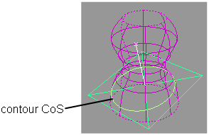
Create curves on surface from contour data
To create a curve-on-surface where the surface intersects a plane:
- Pick the surfaces on which you want to create curves-on-surface.
- Choose Evaluate > Surface Evaluate > Contour
 .
. The Contour control window opens and the contour manipulator appears.
- Click the Go button.
- Use the manipulator to change the position and orientation of the plane, or type exact values in the Plane Origin and Plane Normal fields of the Contour window.
The curve-on-surface updates as the plane is modified.
If Auto Update is off, click Update to create the curve-on-surface.
- Click on additional surfaces to evaluate them, or deselect active surfaces.
- Click the Undo All button in the control window to remove the curves-on-surface.
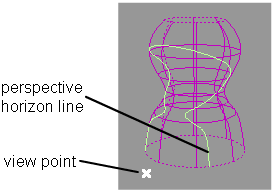
Create curves on surface from horizon data
To create a curve-on-surface across the horizon as seen from a certain angle:
- Pick the surfaces on which you want to create curves-on-surface.
- Choose Evaluate > Surface Evaluate > Horizon
 .
. The Horizon control window opens, and a view point/direction manipulator appears.
- Click the Go button.
- Set the Horizon Type in the control window.
- If the Horizon Type is Perspective, drag the manipulator to move the viewpoint, or type exact coordinates in the View Point fields in the window.
If the Horizon Type is Orthogonal, rotate the manipulator to change the view direction, or type a direction in the View Direction fields in the window.
The curves-on-surface update as the horizon is modified.
If Auto Update is off, click Update to create the curves-on-surface.
Note:If the horizon you set does not cross the surfaces, the tool will not create any curves-on-surface.
- Click on additional surfaces to evaluate them, or deselect active surfaces.
- Click the Undo All button in the control window to remove the curves-on-surface.
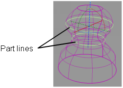
Create curves on surface from parting line data
To create curves-on-surface along draft lines (boundaries of out-of-draft areas) as well as the parting line (0 degree line) given a pull direction.
- Pick the surfaces on which you want to create curves-on-surface.
- Optionally, pick a vector object to use as the pull vector (see Construction > Vector).
- Choose Evaluate > Parting Line
 .
. The Parting Line control window opens, and a manipulator appears.
- Click the Go button in the view window.
- Decide if you need to see the draft lines for both directions of the pull vector, or only one direction, and adjust the Positive Draft Angle and/or Negative Draft Angle accordingly.
- Use the manipulator to change the pull direction, or use the Vector Options in the control window. You can also pick a different vector object. The curves-on-surface update as the pull direction is modified.Tip: If Auto Update is off, click Update to create the curves-on-surface.
- Modify the following options in the control window if needed:
- The Parting Line (0 degree) (on or off)
- The Positive Draft Angle and/or Negative Draft Angle
- The Subdivisions (quality of the curves-on-surface – you can type in a value higher than 6).
- The Vector Options
- The Curve Type (Visual or Geometry)
- Click on, or box-select, additional surfaces to evaluate them, or deselect active surfaces. Note: Box selection can only be used to select surfaces, not meshes or input vectors.
- Click the Undo All button in the control window to remove the curves-on-surface.
You can also use shading to display the in-draft and out-of-draft areas in addition to tolerance zones, by turning on Shade Surfaces. See Shade a surface with its draft angles for more details.