The design of the MP3 player features chamfered sides. Use the Draft and Flange tools to create the side surfaces and a split-line feature.
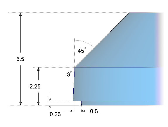
The dimensions for the casing are shown in the following image.
Open the tutorial file (optional)
If you successfully completed part 1, proceed to the next step, Create the side surfaces.
If you were not successful in part 1, open the file called MP3Player_Part1.wire, located in the wire folder of the CourseWare project. This file contains the completed model from part 1.
Create the side surfaces
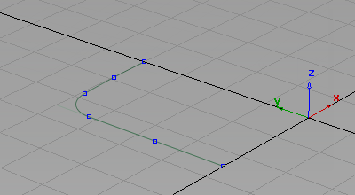
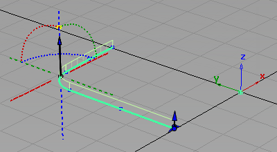
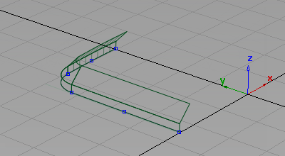
First move your curves away from the centerline in the z-direction to leave some space for a split-line feature you will create later in the tutorial.
- Maximize the Perspective Window.
- Choose Pick > Object
 and drag a pick box over all the curves to select them
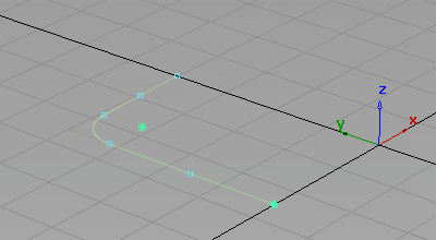
- Choose Transform > Move
 , type r0,0,0.25 and press Enter to move the curves up by 0.25 mm in the z-direction.
 -
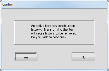
You are asked about losing construction history, which relates to the fillet curve. Answer Yes.
-
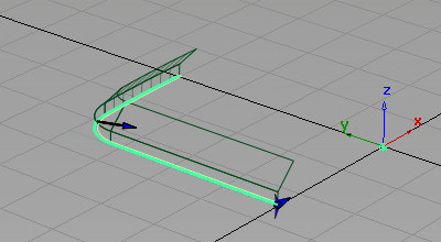
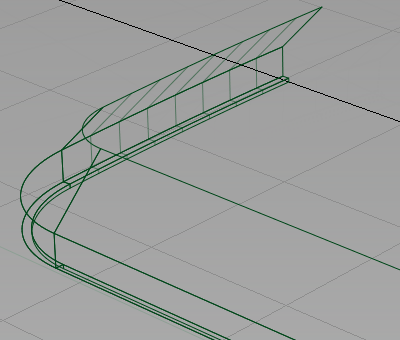
Now create the side wall using a Draft surface.
With the curves still selected, choose Surfaces > Multi-Surface Draft
 . Double-click the icon to open the option window. Start with the default Draft settings, and then modify them after the surface is created.
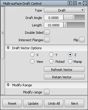
The Draft manipulators display.
- Click Build to create the surface.
The default Draft surface is built. The default draft direction is in the positive z-axis, which is correct for your design.
Tip:To change the draft pull direction for future designs, click the dotted lines and arcs representing the axes.
-
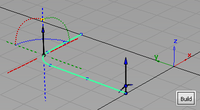
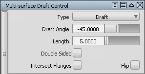
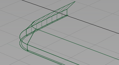
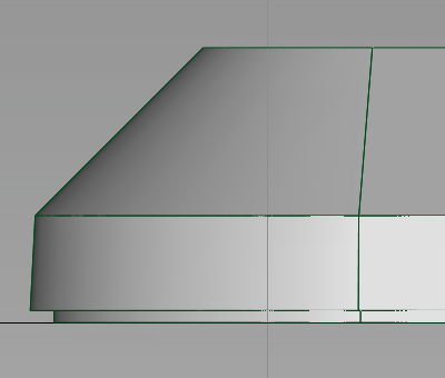
Now modify the Draft Angle and the surface Length to match the required dimensions.
In the Multi-surface Draft Control window, change the settings to a Draft Angle of -3 degrees, and a Length of 2, and click Update.
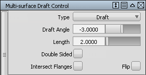
The Draft surface is rebuilt to the new settings.
- Choose Pick > Nothing
 to complete the surface creation.
 -
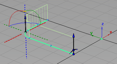
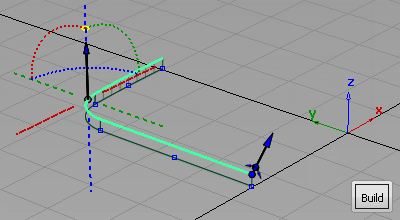
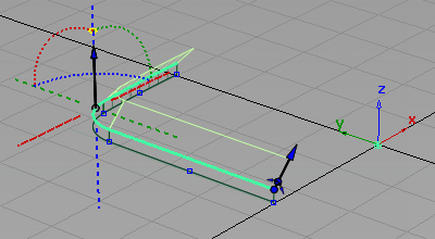
Now build the chamfered surfaces.
Double-click the Multi-Surface Draft icon to open the option window again. Change the settings to a Draft Angle of -45 degrees, and a Length of 5.
 Note:
Note:Build the chamfered surface to an approximate length. The front face of the MP3 player is used later to trim the side walls to the correct height.
-
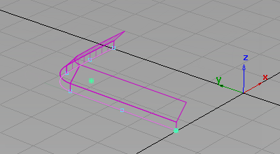
Pick the three top edges of the draft surfaces as the input curves for the new draft surfaces.
-
Click Build to create the chamfered surfaces.
- Choose Pick > Nothing to complete the Draft surfaces.
Create the split-line
Next use the Flange surface to create the small split-line feature at the centerline.
The Flange surface can only be built from a surface edge, not a curve, because it measures its angle from the surface edge, not from a draft direction. So first template your curves to make it easier to select the surface edges.
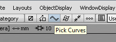
- Choose Pick > Component
 and modify the options so that only curves are selected. Tip:
You can either double-click the Pick > Component icon to set pick options in the option window, or you can use the small icons below the menu bar, as shown in the following image.
- Drag a pick box across the model. Only the curves are selected.
- Choose ObjectDisplay > Template
 to turn the selected curves into a template.
 -
Now create some small Flange surfaces to represent the split-line detail.
Choose Surfaces > Multi-Surface Draft
. Double-click the icon to open the option window. -
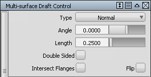
Change the constructionType from Draft to Normal.
Change the Angle to 3, and change the Length to 0.5.
Note:The angle of three degrees compensates for the draft angle of three degrees on the sidewalls. So the flange surfaces are built parallel to the ground plane.

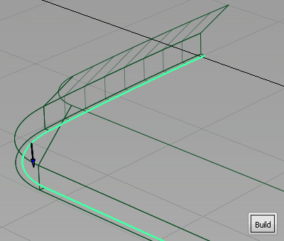
- Click the lower edges of the side walls.
Click Build. The small flange surfaces are created.
- Choose Pick > Nothing to complete the Flange surface.
-
To finish off the sidewalls, create another set of flange surfaces to meet the centerline.
Choose Surfaces > Multi-Surface Draft
again, and double-click the icon to open the option window. -
Change the Angle to 0 and the Length to 0.25.
- Choose the three edges of the flange surface you created and click Build.
- Choose Pick > Nothing to complete the Flange surface.
The side profile of the surfaces shows how the draft angles and split-line detail have been accurately created.
Save your work
- Choose File > Save As
 to save the current scene.
 - Save your work in the wire folder of the Lessons project.
- Name your file myMP3Player2.wire.