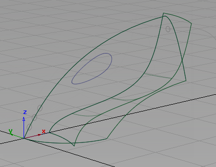
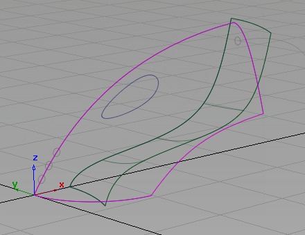
A common way to combine NURBS surfaces is to intersect the surfaces, then trim them where the two surfaces cross each other. Use this approach with the upper and lower surfaces of the vacuum cleaner.
First, intersect the surfaces. When you intersect surfaces, you create curves-on-surface, which are lines that are created on the surfaces where the surfaces intersect. Then trim the intersecting surfaces along the curves-on-surface, so the unnecessary surface areas are discarded, and only the necessary surface areas remain.
Open the tutorial file (optional)
If you successfully completed part 1, you can proceed directly to the next step, Intersect the upper and lower surfaces.
If you were not successful in part 1, open the file called vacuum_Part1.wire, located in the wire folder of the CourseWare project. This file contains the completed model from Ppart 1.
Intersect the upper and lower surfaces
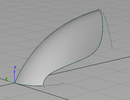
Now, intersect the upper and lower surfaces to create the body shape.
- Click the wireframe icon in the Diagnostic Shade area of the Control Panel to remove the shading.
- Choose Surface Edit > Create CurvesOnSurface > Intersect
 . This tool creates the curves-on-surface that are used to trim the surfaces.
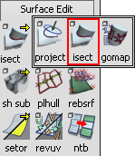
- You are prompted to select the surface(s) to intersect.
Use the
 to click the upper surface to select it. If the pick chooser appears, pick the rail surface, not the curve.
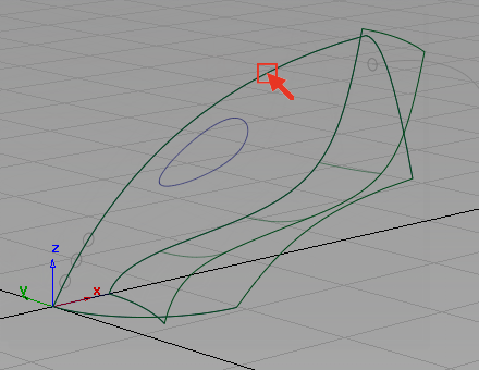
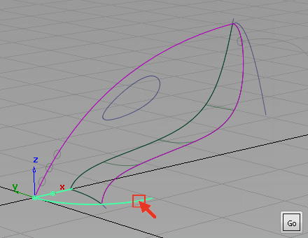
The surface is highlighted and a Go button appears in the lower right corner of the view.
Click Go to select the first surface to intersect.
The surface is highlighted in pink.
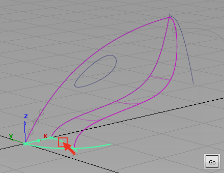
- You are prompted to select the intersecting surface.
Click the lower surface to intersect it with the upper surface.
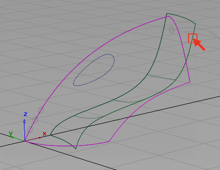
The surfaces are intersected. Two curves-on-surface are created, one on each surface.
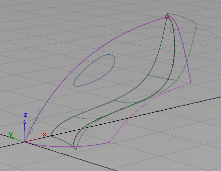
By default, the Intersect tool creates a curve-on-surface on each surface so each surface can be trimmed.
Both surfaces are now drawn with a dotted outline to indicate that each has a curve-on-surface.
- Choose Pick > Object Types > Curve on Surface
 .
. - Drag a pick box around the intersected surfaces to pick the curves-on-surface.
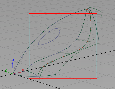
The highlighted curves that appear are the two curves-on-surface. It looks as though there is only one curve-on-surface, but there are two in the same location, one on the upper surface, and one on the lower surface.
- Choose Pick > Nothing
 to unpick the curves-on-surface.
Trim the surfaces
Now, trim off the excess from the upper and lower surfaces.
A trimmed surface is not cut; it exists in a hidden form that does not render or affect modeling. While performing a trim, you can easily discard part of a trimmed surface by selecting the unwanted portion of the geometry and clicking the Divide button that appears at the bottom right corner of the screen.
- Choose Surface Edit > Trim > Trim Surface
 .
. - You are prompted to select a surface to trim.
Pick the upper surface.

- You are then prompted to select one of the following:
Shift select to add or remove surfaces or click or box select to select trim regions.
The last option allows you to trim away the excess parts of the surface, so respond to this prompt.
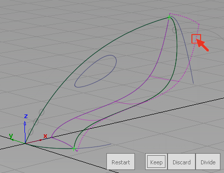
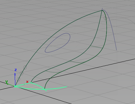
Click any part of the upper surface on the inside part that you want to keep.
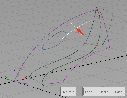
The Trim tool places an indicator where you clicked and the buttons in the bottom right corner of the view become available.
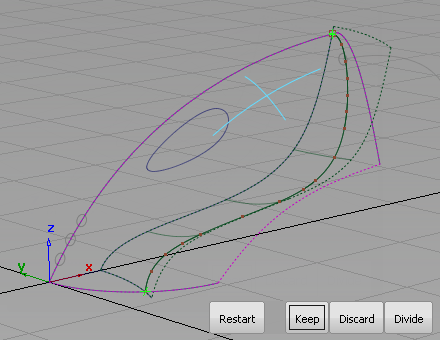
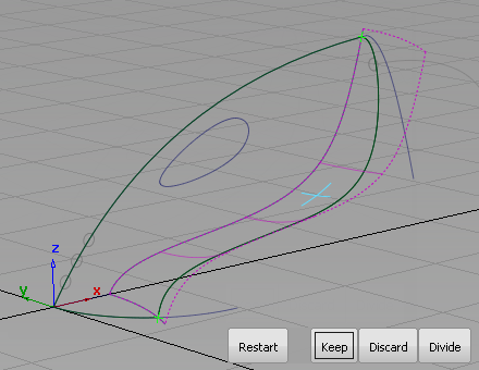
- Click the Keep button.
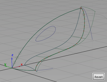
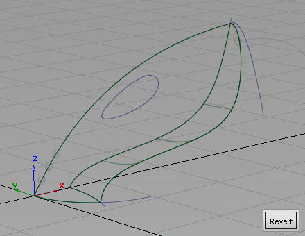
The upper surface is trimmed.
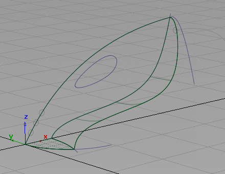
- Repeat steps 2 through 4 to trim the lower surface.
Create the nozzle surface
Next, create a planar surface across the mouth of the nozzle to complete the exterior shape of the vacuum body.
- Choose the Surfaces > Planar Surfaces > Set planar
 tool.
tool. -
You are prompted to select a curve.
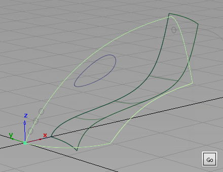
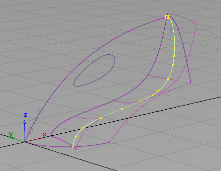
- Click the straight-line curve along the center grid line to select it as the first curve for the planar surface.
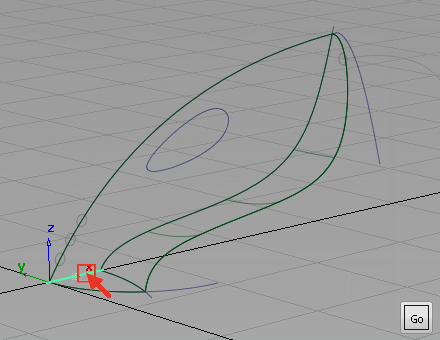
The curve is selected and a Go button appears in the bottom right corner of the view.
You are prompted to select another curve.
- Click the front nozzle curve to select it as the second curve for the planar surface. If the pick chooser appears, make sure that you pick the curve, not the surface edge.
The curve is selected, and you are prompted to select another curve.
- Click the rear nozzle curve to select it as the third curve for the planar surface.
The curve is selected. The three curves form a closed region within which the planar surface is created.
- Click Go to create the planar surface.
The surface is created and displays with a yellow grid.
- Choose Pick > Nothing to deselect the planar surface.
- Use Diagnostic Shade in the Control Panel to view the model.
Save your work
- Choose File > Save As
 to save the current scene.
 - Save your work in the wire folder of the Lessons project.
- Name your file myvacuum2.wire.