Trims or splits surfaces using curves-on-surface or cross sections.
Trim Control
- 3D Trimming
-
If this box is checked, you can trim the surface along projected curves and cross sections, or you can select a surface and generate a trimming curve automatically from the intersection with the target surface. By default it is unchecked.
- Method
-
Displays when 3D Trimming is selected.
Project – Creates trimming curves by projecting the selected curves onto the target surface.
Intersect – Creates a trimming curve from the intersection of the selected surface and the target surface.
You can use the Project or Intersect method in a single trimming operation by toggling back and forth between them.
Vector Options
These options are only available if 3D Trimming is turned on.
- X, Y, Z
-
Specifies a projection vector along that axis.
- View
-
Specifies a vector normal to the current view. The vector is not drawn in the view windows.
If the current view is changed, click Refresh View Vector to update the vector.
Note:You can project different curves along different views vectors. However, if you click Refresh View Vector, or select a different vector option, all curves-on-surface are updated to match the current projection vector.
- Picked
-
Lets you specify the name of an existing vector in the Picked Vector field, or pick the vector in the view.
- Normal
-
The curve is projected onto each point on the surface along the normal at that point, instead of along a single vector direction.
- Picked Vector
-
This text field only appears when Picked is selected. It displays the name of the selected vector object. Alternatively, you can type in the name of a vector object.
- Refresh Vector
-
This button only appears if View is selected. Click it to update the vector if the view has been modified
- Retain Vector
-
Click this button to create a vector construction object in the view windows.Otherwise, the tool uses the vector direction you specified, but you are not able to see and re-use the vector.
Display Options
- Show Intersections
-
If this box is checked, green locators indicate the intersections between the trim curves, and between the trim curves and trim surfaces. Yellow locators indicate trim curve endpoints that do not intersect any other curve-on-surface or trim surface edge.
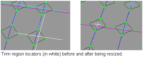
- Region Selector U Size/V Size
-
The relative size of the trim region selectors in the U and V parametric directions on the surface. Adjust these sliders if the selectors (crosses) appear too small or too large on your model. The values range from 0.01 to 2.0.
 Note:
Note:The Shrink Surface option has been replaced by a plug-in called shrinkToTrim which can be loaded through Utilities > Plug-in Manager
 . shrinkToTrim shrinks the UV parameters of the underlying surface to cover only the visible (non-trimmed) parts of the surface. This functionality is useful when applying label-style textures to the surface.
Control Options
- Chain Select
-
If this box is checked, selecting a curve to project also selects all other curves that are tangent continuous with it.
- Create History
-
If this box is checked, the projected curves have construction history. Editing or transforming the curves and surfaces causes the projection and trim operations to be re-executed.
This option is only available if 3D Trimming is turned on.